
Method of measuring properties of an object with acoustically induced electromagnetic waves

a technology of electromagnetic waves and properties, applied in the direction of magnetic field measurement using superconductive devices, instruments, applications, etc., can solve the problems of high field generating apparatus, insufficient position and time resolution of active site, and inability to use this method for human body use, etc., to achieve high position resolution

Active Publication Date: 2012-08-30
JAPAN SCI & TECH CORP
View PDF4 Cites 4 Cited by
  • Summary
  • Abstract
  • Description
  • Claims
  • Application Information

AI Technical Summary

Benefits of technology

[0046]According to the method and apparatus of the present invention, irradiating a measurable object with acoustic waves followed by measuring electromagnetic waves generated from the measurable object allows any one of electric, magnetic and electromagnetic mechanical properties of the measurable object to be determined from any one or a combination of intensity, phase and frequency characteristic of the electromagnetic waves measured. As an electric property of the measurable object, any one or a combination of electric field, dielectric constant, spatial gradient of electric field or dielectric constant, concentration, mass, size, shape, number of charges of charged particles that the measurable object possesses or interaction force with their surrounding medium can be measured of a change or changes thereof. As a magnetic property of the measurable object, magnetization due to electron spin or nuclear spin, or acousto-magnetic resonance due to electron spin or nuclear spin thereof can be measured. As an electromagnetic mechanical property of the measurable object, piezoelectric or magnetostriction property of the measurable object can be measured. Accordingly, measuring a change or changes in these property values in a living body, colloidal solution, liquid crystal, solid electrolyte, ionic crystal, semiconductor, dielectric, metal, magnetic material or magnetic fluid or a composite material thereof or a structure or a functional device composed of such a material is useful in clarifying the related phenomena. Especially, using the present invention in the determination of an active site in a brain makes it possible to identify an activated site at an extremely high position resolution.

Problems solved by technology

While in the measurement of an action potential in the nervous system, a method is usually taken in which to directly insert an electrode into the body, use cannot be made of this method for a human body, inter alia for its brain tissue but necessarily of a noninvasive measuring method to identify an active region from the outside of the human body without harming the body part.
As a result, their position and time resolutions for an active site are not sufficient in elucidating a relation between a human mental activity and a brain's action or in serving for disease therapy.
They require a cyclotron accelerator for producing positrons, a high field generating apparatus for nuclear magnetic resonance or the like and are extremely high in apparatus cost.
This method in which a position is estimated on the basis of a magnetic field distribution and hence determined indirectly is not enough in position resolution.
Especially if a plurality of sites are active simultaneously, their identification then becomes difficult.
There is also the problem that it is difficult to detect information from a deep part and an electric current passed towards a normal to a surface.

Method used


Image

  • Method of measuring properties of an object with acoustically induced electromagnetic waves
  • Method of measuring properties of an object with acoustically induced electromagnetic waves
  • Method of measuring properties of an object with acoustically induced electromagnetic waves

Examples


example 1

[0170]The present invention in further detail with reference to specific examples will be mentioned.

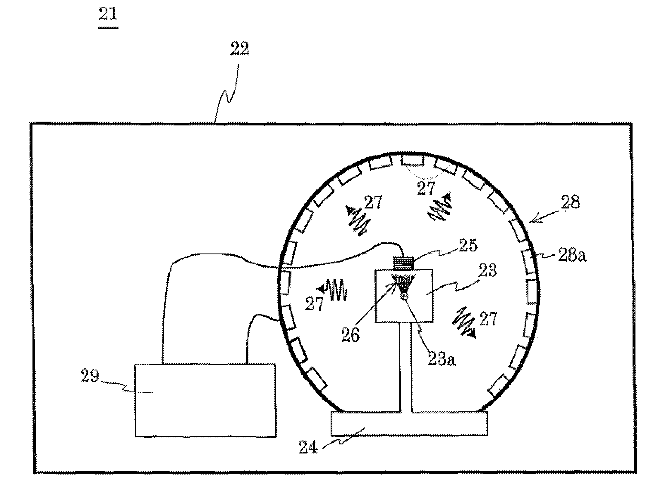
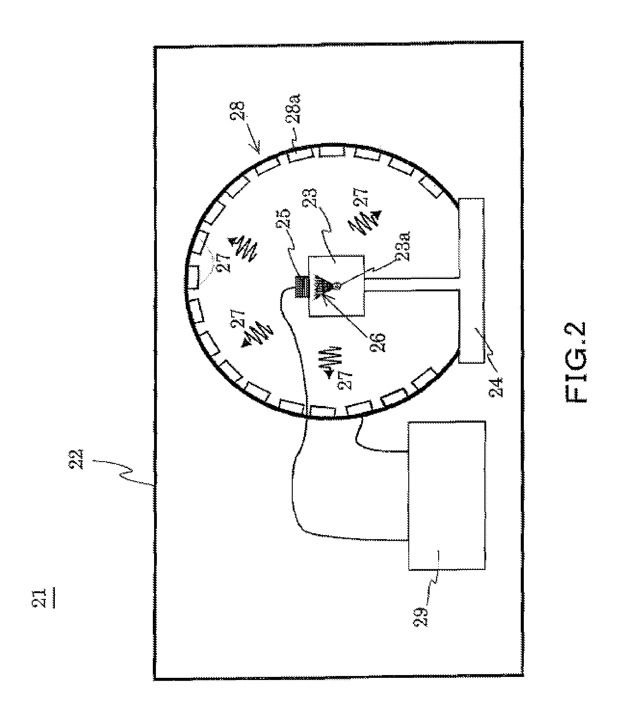
[0171]FIG. 13 diagrammatically illustrates the structure of an apparatus measuring a property of an object with acoustically induced electromagnetic waves in Example 1, showing at (a) the apparatus structure, at (b) a modification of ultrasonic probe and at (c) a waveform of ultrasonic waves, respectively.

[0172]As shown in FIG. 13(a), the measuring apparatus 21 comprises the anechoic chamber 22, the retainer table for holding thereon a measurable object 23 disposed in the anechoic chamber 22, the acoustic generator 25 disposed adjacent to or in contact with the object 23, a loop antenna 28 for receiving electromagnetic waves generated from a region 23a on which acoustic waves 26 are focused that the acoustic generator 25 generates, and the control, measure and process unit 29 (not shown) for controllably driving the acoustic generator and measuring and processing electromagnetic wave ...

example 2

[0174]An apparatus for measuring a property of charged particles was prepared which was identical to that in Example 1 except that the output of the third small amplifier was heterodyne-detected. The mixer used was a double balanced mixer.

example 3

[0175]Using a semiconductor made of GaAs crystal as the measurable object 23, acoustically induced electromagnetic waves were detected with the apparatus of Example 1 or 2 for measuring a property of charged particles.

[0176]FIG. 14 illustrates detected waveforms of acoustically induced electromagnetic waves from semiconductor GaAs crystal as the object 23, showing at (a) an ultrasonic waveform, at (b) a waveform obtained in the property measuring apparatus in Example 1 and at (c) a waveform obtained in a property measuring apparatus in Example 2. In the graph of FIG. 14, the abscissa axis represents time (in μs) and the ordinate axis represents the signal intensity (in arbitrary scale). The GaAs used was a non-doped crystal of 350 μm thickness. Its [110] axis was aligned in orientation with the direction of wave number vector k of the incident ultrasonic waves. The GaAs is a material whose piezoelectric coefficient is expressed by equation (7) below.

|d14GaAs|=2.7 pC / N  (7)

[0177]Acco...


PUM


Abstract

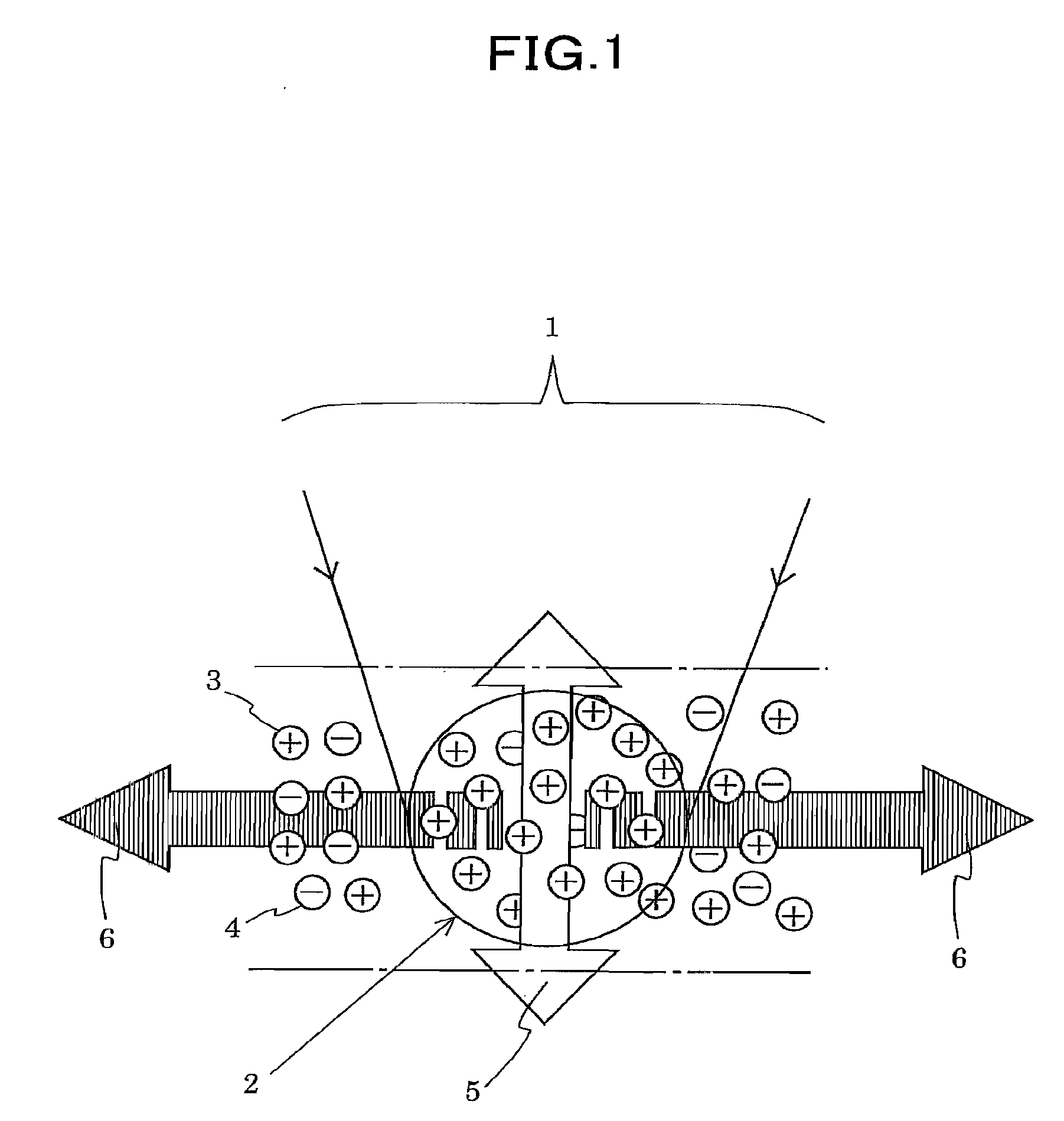
A measuring method and apparatus in which a measurable object (23) is irradiated with acoustic waves to measure a change in property value of charged particles in the object from electromagnetic waves induced thereby. A part (2) of the measurable object irradiated with an acoustic focused beam (1) is in a charge distribution state in which positive charged particles (3) are greater in number in the part (2) where electromagnetic waves induced by positive charged particles (3) are not canceled by those induced by negative charged particles (4) and where net electromagnetic waves (6) are induced. Since a change in concentration of positive charged particles (3) and / or negative charged particles (4) changes the intensity of electromagnetic waves (6), it is possible to know such a change in concentration of the charged particles from a change in intensity of electromagnetic waves (6).

Description

TECHNICAL FIELD[0001]The present invention relates to a method of and an apparatus for measuring properties of an object of every sort, including a human body, which when acoustically vibrated may be capable of emitting electromagnetic waves, from such electromagnetic waves induced by applicable sound waves. The present invention relates in particular to a technique using such a method for the measurement of an active site of a brain.BACKGROUND ART[0002]In the interest of elucidating a relation between a human mental activity and a brain's action and in an effort to specify a lesion in brain's disease therapeutics, attempts have been made to identify a neural active site of the brain. Neurons in a neural activity control an ion concentration to form a charge distribution and transmit information through propagation of a potential created by the charge distribution, namely of an action potential (see Non-patent Reference 1). Thus, the most direct information source that can identify ...

Claims


Application Information

Patent Timeline
Patent Type & Authority Applications(United States)
IPC IPC(8): A61B5/055A61B5/05A61B6/00
CPCA61B5/0093A61B5/05A61B5/4064A61B5/7203A61B5/7225A61B5/7228G01R33/1269A61B8/00A61B2562/0223A61B2562/18G01R33/0213G01R33/035A61B5/7235
Inventor IKUSHIMA, KENJIKOMIYAMA, SUSUMU
Owner JAPAN SCI & TECH CORP
Learn More