Check patentability & draft patents in minutes with Patsnap Eureka AI!

Electronic endoscopy system

A technology of electronic endoscopy and charge, applied in the direction of endoscopy, medical science, diagnosis, etc., to achieve the effect of ensuring comparative observation and eliminating the formation of mixed images

Inactive Publication Date: 2011-12-07
FUJIFILM CORP
View PDF6 Cites 37 Cited by
  • Summary
  • Abstract
  • Description
  • Claims
  • Application Information

AI Technical Summary

Problems solved by technology

[0012] In this way, if a CMOS image sensor is used for simultaneous shooting, a blank frame will be generated between two frames with different illumination lights, so only switching the illumination light cannot ensure the synchronization between multiple images like a CCD image sensor. sex

Method used


Image

  • Electronic endoscopy system
  • Electronic endoscopy system
  • Electronic endoscopy system

Examples


Embodiment Construction

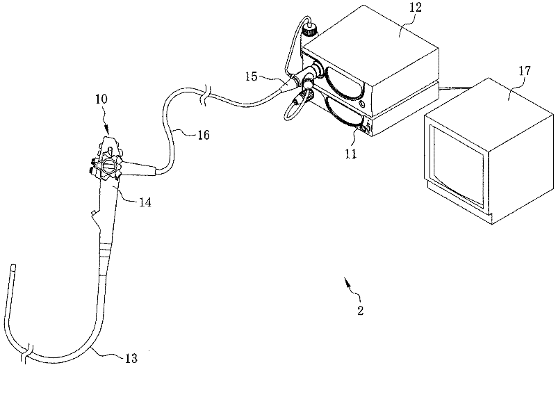
[0036] figure 1 Among them, the electronic endoscope system 2 is composed of an electronic endoscope 10 , a processor device 11 , and a light source device 12 . As is well known, the electronic endoscope 10 has a flexible insertion portion 13 inserted into the body cavity of the subject (patient) to be inspected, an operation portion 14 connected to the base end portion of the insertion portion 13, a processor device 11, and a light source device. The connector 15 of 12 and the universal cord 16 between the operation part 14 and the connector 15 are connected.

[0037] Such as figure 2 As shown, the front end surface of the insertion portion 13 is provided with an imaging window 20, an illumination window 21, and the like. A CMOS type image sensor (hereinafter referred to as a CMOS sensor) 23 is arranged in the depth of the imaging window 20 via an imaging optical system 22 composed of a lens group and a prism. An illumination lens 25 is arranged behind the illumination w...


PUM


Abstract

PROBLEM TO BE SOLVED: To permit observation images by different rays of illumination light to be simultaneously observed even by using a CMOS type image sensor. SOLUTION: The electronic endoscope 10 has a CMOS type image sensor (CMOS sensor) 23. The vertical scanning circuit 51 of the CMOS sensor 23 is structured so as to enable it to read an imaging signal every other horizontal line and to discharge the signal electric charge of all pixels 56 of the CMOS sensor 23 to a drain (collective resetting of all pixels) through a resetting transistor M3. When a simultaneous photographing mode to obtain each observation image is chosen by irradiating ordinary light (white light) and special light of a narrow wavelength zone, the system turns off the illumination light while it reads the imaging signal every other horizontal line by the vertical scanning circuit 51. The system adjusts the starting timing of electric charge accumulation of the CMOS sensor 23 by carrying out collective resetting of all pixels by the vertical scanning circuit 51 and changes the illumination light by the accumulation period of the CMOS sensor 23. COPYRIGHT: (C)2012,JPO&INPIT

Description

technical field [0001] The present invention relates to an electronic endoscope system having a CMOS image sensor, and more specifically, to an electronic endoscope system for imaging an observation site while switching illumination light. Background technique [0002] Conventionally, in the medical field, examinations using electronic endoscopes have been widely used. The electronic endoscope includes an insertion unit for insertion into a body cavity of a subject (patient) and an operation unit for operating the insertion unit. An illumination window for illuminating the observation site in the body cavity and an imaging window for imaging the observation site with the solid-state imaging device are provided at the front end of the insertion part. The electronic endoscope is connected to the processor device and the light source device through flexible wires or connectors. The processor device performs various processes on the imaging signal output from the solid-state i...

Claims


Application Information

Patent Timeline
IPC IPC(8): A61B1/05
Inventor 远藤安土村山任饭田孝之
Owner FUJIFILM CORP
Features
  • R&D
  • Intellectual Property
  • Life Sciences
  • Materials
  • Tech Scout
  • Unparalleled Data Quality
  • Higher Quality Content
  • 60% Fewer Hallucinations
Learn More