Hole group processing method for flexible guide rail based on coordinate system of hole-making equipment

A technology of equipment coordinate system and flexible guide rail, which is applied in the field of mechanical processing to achieve the effect of improving processing efficiency and simplifying calculation steps

Inactive Publication Date: 2011-12-07
SHANGHAI JIAO TONG UNIV
View PDF4 Cites 19 Cited by
  • Summary
  • Abstract
  • Description
  • Claims
  • Application Information

AI Technical Summary

Problems solved by technology

However, there is no record about the flexible hole making that is specially applied to airc

Method used


Image

  • Hole group processing method for flexible guide rail based on coordinate system of hole-making equipment
  • Hole group processing method for flexible guide rail based on coordinate system of hole-making equipment
  • Hole group processing method for flexible guide rail based on coordinate system of hole-making equipment

Examples


Example Embodiment

[0017] Example

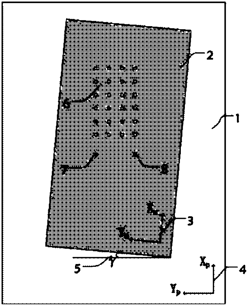
[0018] like figure 1 As shown, the application environment of this embodiment includes: workpiece 1 and equipment processing range 2, 3 is the machine tool coordinate system related to the machine tool hardware, 4 is the workpiece coordinate system related to the workpiece, the value of γ angle 5 is the value of the deflection angle, That is, the included angle between Xm and Xp, 6 is a group of holes to be processed, 7 and 8 are two process positioning K holes respectively.

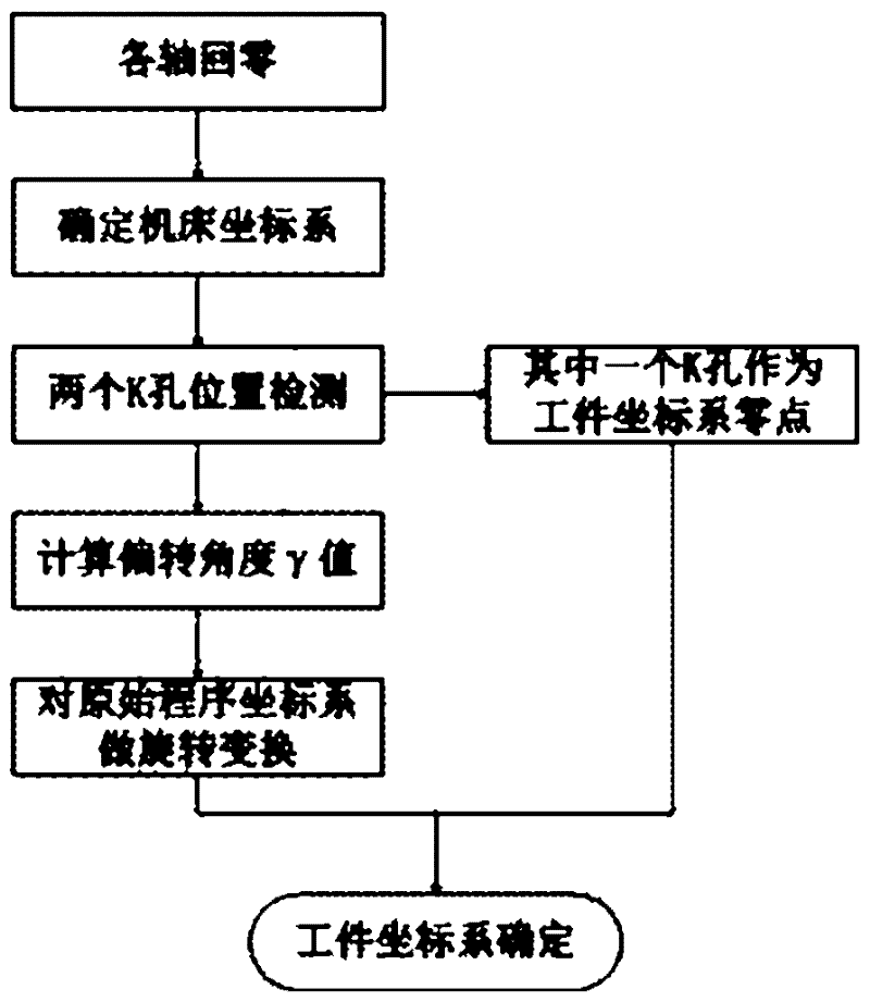
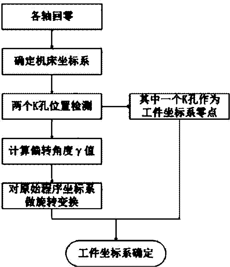
[0019] like figure 2 As shown, the process of this embodiment includes:

[0020] The first step, the process of returning to zero for each axis, determines the coordinate system of the machine tool: make the X-axis and Y-axis of the machine tool automatically return to zero. After the zero point of each machine tool axis is determined, the direction of each axis is the direction of the axis according to the direction limited by each axis of the equipment itself. At this time, the coo...


PUM


Abstract

The invention relates to a flexible guide rail hole group machining method based on drilling equipment coordinate system determination in the field of machining. The method comprises the following steps of: calculating a difference between an actual value and a preset value of an angle of a connecting line of two K holes to obtain a deflection angle gamma; and performing -gamma angular coordinate transformation on a coordinate system of a machining code and setting one of the K holes as a workpiece zero point so as to eliminate deflection error. By the flexible guide rail hole group machining method, system error of the deflection angle between a machine coordinate system and a workpiece coordinate system can be overcome conveniently, and high-precision and high-efficiency running of the equipment can be realized.

Description

technical field [0001] The invention relates to a method in the technical field of mechanical processing, in particular to a method for processing hole groups of a flexible guide rail determined based on the coordinate system of a hole-making equipment. Background technique [0002] The coordinate systems commonly used in existing machining are machine coordinate system and workpiece coordinate system, also called program coordinate system. By setting a fixed reference point (assumed to be (X, Y, Z, B)) in the mechanical coordinate system of the machine tool. The function of this reference point is mainly to give a position to the machine tool itself. Because the system will set the current position as (0, 0, 0, 0) no matter which position the tool post stays after each startup, which will inevitably lead to inconsistent benchmarks, so the first step of each startup is used as a reference Point regression (some are called zero return), that is, to determine the origin (0, ...

Claims


Application Information

Patent Timeline
IPC IPC(8): B23B35/00
Inventor 姚振强胡永祥冰峰张冉冉徐晓霞
Owner SHANGHAI JIAO TONG UNIV
Why Eureka
Try Eureka