Steady frame of a machining cutting machine tool

A technology for cutting machine tools and steady rests, which is applied to metal processing machine parts, metal processing equipment, manufacturing tools, etc. It can solve the problems of difficult adjustment of force, loose force of the workpiece, and locking, so as to achieve uniform force and reduce The effect of being locked and beneficial to processing

Inactive Publication Date: 2011-12-07
CHENGDU KESHENG PETROLEUM TECH +1
View PDF7 Cites 12 Cited by
  • Summary
  • Abstract
  • Description
  • Claims
  • Application Information

AI Technical Summary

Problems solved by technology

[0003] The purpose of the present invention is to overcome the problem that the current steady frame is difficult to adjust the force when clamping the workpiece, which easily leads to the loosening of the workpiece to form an ellipse on the end face of the workpiece or the locking caused by excessive force, and to provide a center frame for machining and cutting machine tools

Method used


Image

  • Steady frame of a machining cutting machine tool
  • Steady frame of a machining cutting machine tool
  • Steady frame of a machining cutting machine tool

Examples


Embodiment

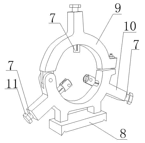
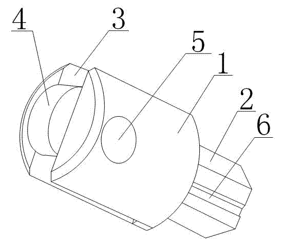
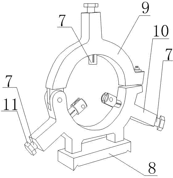
[0018] Such as Figures 1 to 2 As shown, the center frame of a machining and cutting machine tool of the present invention includes a mounting seat 8, a center frame body 9 is arranged on the mounting seat 8, three adjustment cylinders 10 are arranged on the center frame body 9, and three adjustment cylinders 10 are arranged on the adjustment cylinder 10. There is a turntable 11, and the turntable 11 is connected with the top wheel through the screw rod 7 in the adjustment barrel 10. The adjustment barrel 10 runs through the center frame body 9, and one end of the three adjustment barrels 10 located in the center frame body 9 is equipped with a top wheel. The top wheel includes The top cylinder 1, the top cylinder 1 is cylindrical as a whole, and one end surface of the top cylinder 1 is connected with a hexagonal column socket 2, and the socket 2 is provided with a guide groove 6 parallel to the axis of the top cylinder 1. The adjustment cylinder 10 is provided with a guide ba...


PUM


Abstract

The invention discloses a center frame of a machining and cutting machine tool, comprising a mounting seat (8), a center frame body (9) is arranged on the mounting seat (8), and three adjustment cylinders are arranged on the center frame body (9) (10), the adjustment cylinder (10) runs through the center frame body (9), and the top wheel is installed at one end of the three adjustment cylinders (10) located in the center frame body (9). In the present invention, a top wheel is installed on the adjustment cylinder of the center frame body, which converts the friction force between the workpiece and the center frame body into rolling friction force, which reduces the situation that the workpiece is locked. At the same time, driven by the turntable, it can Adjust the force between the top wheel and the workpiece so that the workpiece is evenly stressed.

Description

technical field [0001] The invention relates to an auxiliary device in the machining and cutting process, in particular to a center frame of a machining and cutting machine tool. Background technique [0002] In the machining industry, especially in the machining of slender workpieces, steady rests are often used. The center frame is an auxiliary device for radially supporting the rotating workpiece during processing. When processing slender shaft parts, the length-to-diameter ratio L / D>15, in order to prevent the workpiece from being bent and deformed by the radial cutting force, it is commonly used The steady frame is used as an auxiliary support to increase the rigidity of the workpiece. During processing, there is no relative axial movement with the workpiece. The steady frame should be fixed on the bed, and the center frame should be roughly aligned with a needle. After lubricating oil is applied, the bed rotates at a low speed to adjust the speed according to the t...

Claims


Application Information

Patent Timeline
Patent Type & Authority Applications(China)
IPC IPC(8): B23Q1/76
Inventor 贺昶明
Owner CHENGDU KESHENG PETROLEUM TECH
Why Eureka
Try Eureka