Mechanical pile-clamping case

A mechanical, pile-clamping box technology, applied in sheet pile wall, construction, infrastructure engineering, etc., can solve the problems of short service life, high maintenance probability and high manufacturing cost, and achieve long service life, low maintenance probability, and high manufacturing cost. simple effect

Inactive Publication Date: 2013-06-26
ANHUI LIDA IND
View PDF6 Cites 0 Cited by
  • Summary
  • Abstract
  • Description
  • Claims
  • Application Information

AI Technical Summary

Problems solved by technology

[0002] In the prior art, the pile clamping box of the static pile driver is generally hydraulic, and there are technical problems such as sliding piles and bursting piles during use, and there are also high manufacturing costs, short service life, high maintenance probability, and complex structure. , manufacturing difficulty and many other deficiencies

Method used


Image

  • Mechanical pile-clamping case
  • Mechanical pile-clamping case

Examples


Embodiment Construction

[0010] In order to make the technical means, creative features, goals and effects achieved by the present invention easy to understand, the present invention will be further elaborated below in conjunction with specific embodiments and illustrations.

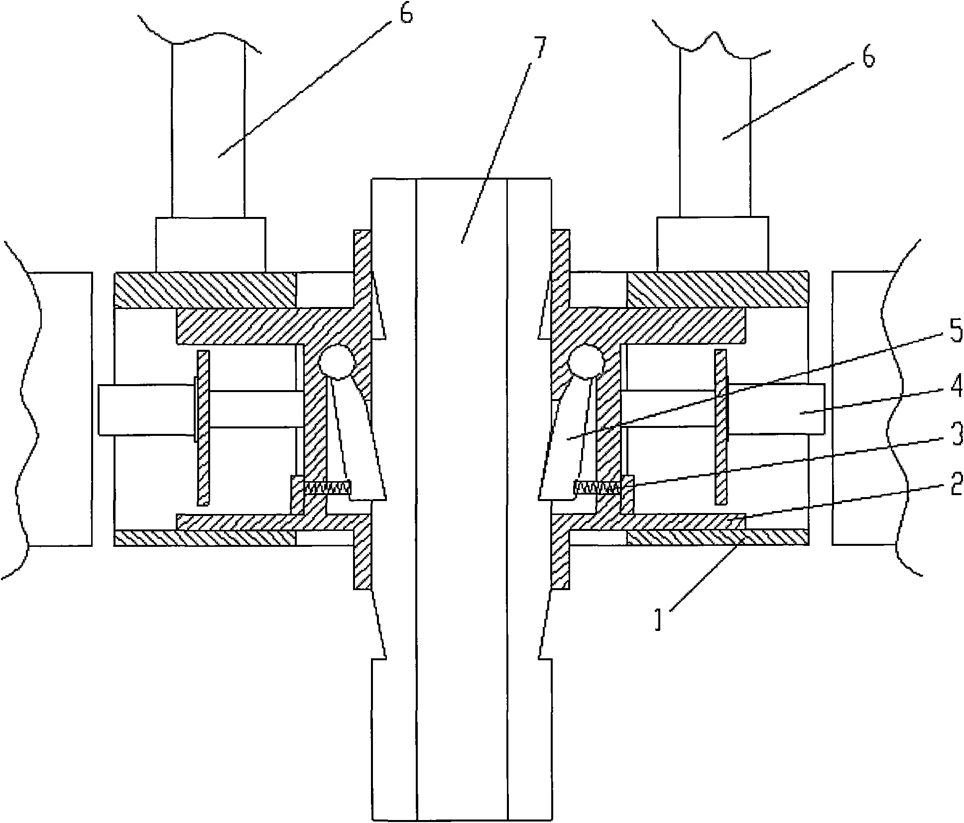
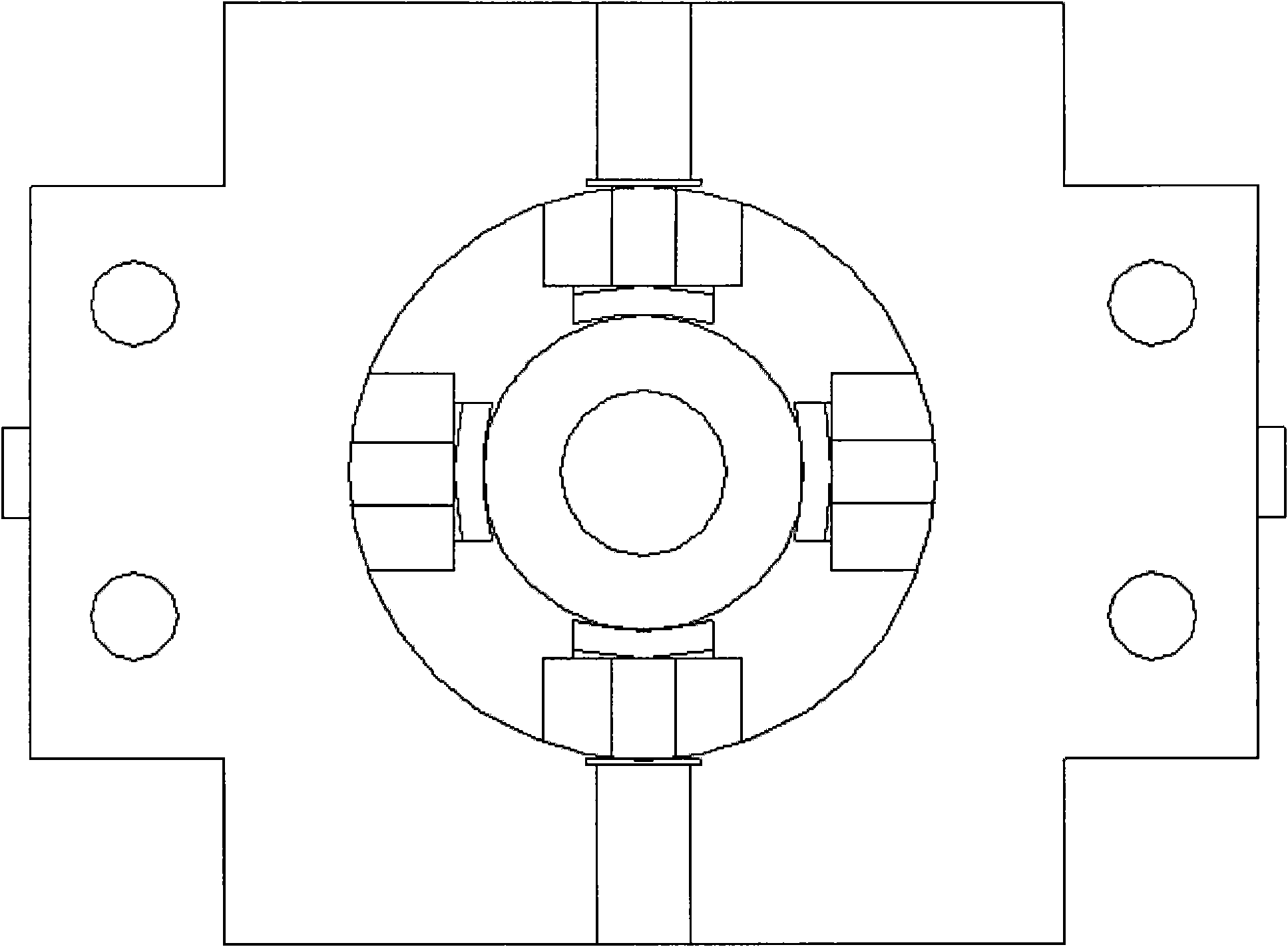
[0011] Such as figure 1 , figure 2 As shown, a mechanical pile box includes a pile box main body 1 whose upper end is connected to the main pressure oil cylinder 6. A circular workpiece pile hole is opened in the middle of the pile box main body 1. Two pairs of movable integral jaws 2 connected with the oil cylinder 4, the oil cylinder 4 is fixed in the main body 1 of the pile clamping box, the movable integral jaw 2 is provided with a movable block 5, and one end of the movable block 5 is rotationally connected with the movable integral jaw 2 through a rotating shaft , a spring 3 is provided at one end.

[0012] When the oil cylinder 4 adjusts the stroke, the oil cylinder 4 drives the movable integral jaw 2 to slide back and...


PUM


Abstract

The invention discloses a mechanical pile-clamping case, and relates to a main component of a static pile press. The mechanical pile-clamping case comprises a pile-clamping case main body the upper end of which is connected with a main press cylinder, a round wokpiece pile hole is formed at the center of the pile-clamping case main body, two pairs of movable integrated jaws which are connected with the main press cylinder are arranged in the pile-clamping case main body symmetrically, and movable blocks are arranged on the movable integrated jaws, one end of each movable block is in rotary connection with one movable integrated jaw, and the other end of each movable block is provided with a spring. The mechanical pile-clamping case provided by the invention has the advantages of simple manufacture process, low cost, stable performance, convenience in maintenance, long service life, and low cost which is reduced by 40% as compared with that of the traditional pile-clamping case, completely eliminates the problems of pile breakage and slippage, has low maintenance probability, has prolonged service life, is in no need of jaw replacement when applied to piles in various specifications, and is simple and convenient to operate, and the jaw service life is also prolonged.

Description

Technical field: [0001] The invention relates to a main part of a static pile driver, in particular to a mechanical pile clamping box. Background technique: [0002] In the prior art, the pile clamping box of the static pile driver is generally hydraulic, and there are technical problems such as sliding piles and bursting piles during use, and there are also high manufacturing costs, short service life, high maintenance probability, and complex structure. , Manufacturing difficulty is big etc. many-side deficiencies. Invention content: [0003] The technical problem to be solved by the present invention is to provide a mechanical pile clamping box with simple manufacture, low cost, stable performance, convenient maintenance and long service life. [0004] The technical problem to be solved by the present invention adopts the following technical solutions to realize: [0005] A mechanical pile clamping box, characterized in that it includes a pile clamping box main body w...

Claims


Application Information

Patent Timeline
Patent Type & Authority Patents(China)
IPC IPC(8): E02D7/20
Inventor 刘红鹰刘浩屈金山
Owner ANHUI LIDA IND
Why Eureka
Try Eureka