Method and device for beam pairing between devices

A technology between devices and devices, applied in the field of communication, can solve the problems of long delay and high power consumption of devices

Inactive Publication Date: 2011-12-07
HUAWEI TECH CO LTD +1
View PDF3 Cites 8 Cited by
  • Summary
  • Abstract
  • Description
  • Claims
  • Application Information

AI Technical Summary

Problems solved by technology

[0005] Embodiments of the present invention provide a beam pairing method and device between devices to solve the defects of long delay in the beam pairing process between devices and high power consumption of devices

Method used


Image

  • Method and device for beam pairing between devices
  • Method and device for beam pairing between devices
  • Method and device for beam pairing between devices

Examples


no. 1 example

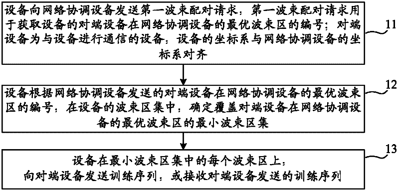
[0062] Figure 1A It is a flow chart of a beam pairing method between devices provided in the first embodiment of the present invention. The device in this embodiment can be a device that sends a training sequence during beam pairing, and its peer device is a device that receives a training sequence; the device in this embodiment can also be a device that receives a training sequence during beam pairing, and its peer device is a device that receives a training sequence. Equipment for training sequences. like Figure 1A As shown, this embodiment includes:

[0063] Step 11: The device sends the first beam pairing request to the network coordination device. The first beam pairing request is used to obtain the number of the peer device of the device in the optimal beam area of ​​the network coordination device; the peer device is the device that communicates with the device , the device coordinate system is aligned with the network coordination device coordinate system.

[0064]...

no. 2 example

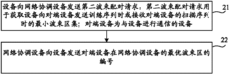
[0143] Figure 6A It is a flowchart of a beam pairing method between devices provided in the second embodiment of the present invention. In the second embodiment, the network coordinating device directly provides the device with the minimum set of beam areas to be scanned during the beam pairing process. like Figure 6A As shown, this embodiment includes:

[0144] Step 61: The network coordination device receives the second beam pairing request sent by the device, and the second beam pairing request is used to obtain the minimum beam area set when the device sends a training sequence to the peer device or receives the scan sequence of the peer device; the peer A device is a device that communicates with a device.

[0145] When performing beam pairing between devices, the device coordinate system is aligned with the network coordination device coordinate system. If the device coordinate system is not aligned with the network coordination device coordinate system, the device ...


PUM


Abstract

The embodiment of the invention provides a method and device for pairing wave beams among devices, wherein the method for pairing the wave beams among devices comprises the steps: the devices send first wave beam pairing requests to a network coordinating device, wherein the first wave beam pairing requests are used for obtaining the number of an optimal wave beam zone of opposite-end devices of the devices in the network coordinating device, the opposite-end devices are used for communicating with the device, and the coordinate system of the devices and the coordinate system of the network coordinating device are aligned; according to the number of the optimal wave beam zone of the opposite-end device in the network coordinating device, sent by the network coordinating device, the devices determine the minimum wave beam zone set of the opposite-end devices in the optimal wave beam zone of the network coordinating device in the wave beam zone set of the devices; and in each wave beam zone in the minimum wave beam zone set, the devices send a training sequence to the opposite-end devices or receive the training sequence sent by the opposite-end devices. According to the embodiment of the invention, the devices can be avoided sending or receiving training sequences in unnecessary wave beam zones, thus delay in pairing of the wave beams among the devices is reduced, and the power consumption of the devices is decreased.

Description

technical field [0001] Embodiments of the present invention relate to communication technologies, and in particular to a method and device for pairing beams between devices. Background technique [0002] Under the existing centralized network architecture, two devices need to perform beam pairing before wireless communication to obtain their respective optimal transmit beams and optimal receive beams, so that the sending end sends data to the receiving end on the optimal transmitting beam, and at the same time The receiving end receives the data from the sending end at the optimal receiving beam. [0003] At present, beam pairing usually adopts a sequential scanning method, as follows: In a symmetrical antenna system, it is assumed that device A has EA receiving beams and EA transmitting beams, and device B has EB receiving beams and EB transmitting beams. Device A sends EB repeated training sequences on each transmit beam, and device A sends a total of EA×EB training seque...

Claims


Application Information

Patent Timeline
Patent Type & Authority Applications(China)
IPC IPC(8): H04B7/04
CPCY02D30/70
Inventor 刘培夏金环徐平平徐祎志
Owner HUAWEI TECH CO LTD
Why Eureka
Try Eureka