Devices for energy conversion, electrical switching and thermal switching

A device, electrode technology, applied in the field of diodes

Inactive Publication Date: 2011-12-07
TEMPRONICS INC
View PDF30 Cites 2 Cited by
  • Summary
  • Abstract
  • Description
  • Claims
  • Application Information

AI Technical Summary

Problems solved by technology

Although this approach can create thermal tunneling gaps, this approach suffers from th

Method used


Image

  • Devices for energy conversion, electrical switching and thermal switching
  • Devices for energy conversion, electrical switching and thermal switching
  • Devices for energy conversion, electrical switching and thermal switching

Examples


Embodiment Construction

[0040] Referring in more detail to the drawings, in which like numerals refer to like elements throughout the several views, there are illustrated exemplary embodiments of the apparatus and processes of the present disclosure.

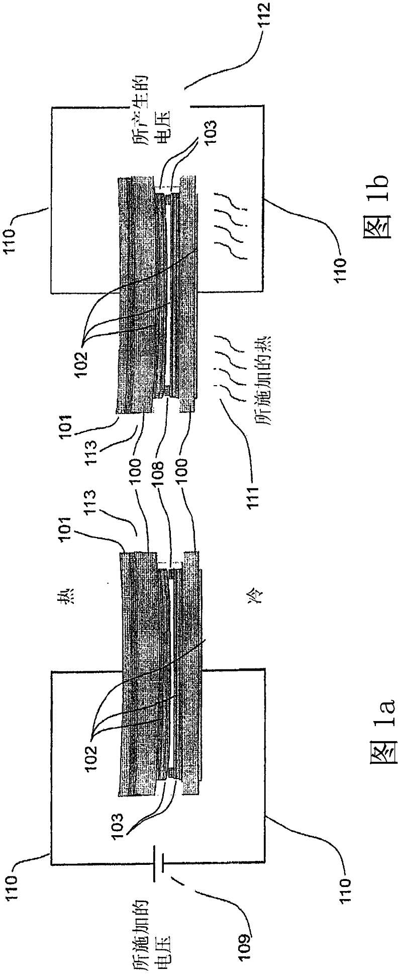
[0041] exist Figure 1a In , two electrodes are shown, one curved and the other substantially flat. A piece of single crystal silicon 100 is used as the substrate, and this substrate is highly doped to a level of 0.001 to 0.01 ohm-em to allow conductivity from top to bottom. Without limitation, other metals or semiconductors may be used for the substrate 100, such as silicon carbide, germanium, gallium arsenide, and low thermal expansion metal alloys such as Kovar. The metal layer 101 and metal layer 102 on each side of the silicon substrate 100 serve to spread the current, allowing this current to flow through the entire area of ​​the silicon substrate 100, thus reducing the resistance of the current flowing from the top to the bottom of each substra...


PUM


Abstract

The present invention discloses an improvement for maintaining nanometer separation between electrodes in tunneling, thermal tunneling, diode, thermionic, thermoelectric, thermophotovoltaic, current limiting, resettable fusing, relays, circuit breakers and other devices the design of. At least one electrode has a curved shape, the curvature of which is changed by temperature. Some embodiments use nanoseparation to limit or stop the electrical current. Other embodiments reduce heat conduction between the two electrodes when compared to the prior art. The result is an electronic device that maintains two close parallel electrodes in a stable equilibrium with a nanogap between the two electrodes over a large area in a simple configuration for ease of manufacturability, and the resulting The devices described above are used to convert heat into electricity for cooling, or to limit or interrupt current flow.

Description

technical field [0001] The present invention relates to diodes, thermionics, tunneling, current limiting, current interrupting and other devices designed with extremely small spacing between electrodes and in some cases also requiring thermal insulation between electrodes. The present invention has particular utility in connection with thermal tunnel generators and heat pumps, and can be applied to similar systems using thermionic and thermoelectric methods, and will be described in connection with such utility, although others are also contemplated. These heat tunnel generators and heat pumps convert heat energy into electricity and can operate in reverse to provide cooling. The invention is also applicable to any device requiring close, parallel spacing between two electrodes between which a voltage is applied or generated. The invention can also be applied to switching devices, such as current limiters, over-temperature protectors, relays, resettable fuses or circuit break...

Claims


Application Information

Patent Timeline
IPC IPC(8): H01L35/34
CPCH01J45/00H01L35/16H01J21/04H10N10/852H10N10/80H10N10/01
Inventor 塔雷克·马坎斯
Owner TEMPRONICS INC
Why Eureka
Try Eureka