
Speed changing air chamber hole seeding apparatus

An air cavity and hole sowing technology, which is applied in the direction of single seed planters and planter parts, can solve the problems that have not been substantially solved, and it is difficult to ensure the stability of negative pressure in the negative pressure cavity, so as to improve the seed collection rate, The effect of improving quality and stability and increasing service life

Inactive Publication Date: 2011-12-14
陈恒
View PDF4 Cites 2 Cited by
  • Summary
  • Abstract
  • Description
  • Claims
  • Application Information

AI Technical Summary

Problems solved by technology

Among them, the air-suction precision seed picker is mainly composed of a negative pressure cavity and a seed suction plate. The seed suction plate is fixed on the end face of the negative pressure cavity. When working, the seed suction plate and the negative pressure cavity rotate relatively. Specifically speaking, the negative pressure chamber is fixed on the bracket, and the suction disk rotates. Such a structure is difficult to ensure the stability of the negative pressure in the negative pressure chamber. The reason is that when the suction disk rotates, the distance between the suction disk and the negative pressure chamber There is an inevitable gap at the joint, which leads to air leakage. The size of the air leakage is an important factor to ensure the stability of the negative pressure of the product. Therefore, technicians in the same industry have been expecting to control the air leakage through the improvement of materials and the design of the matching method, but Due to the structural problems of the design itself, it has not been substantively resolved

Method used


Image

  • Speed changing air chamber hole seeding apparatus
  • Speed changing air chamber hole seeding apparatus
  • Speed changing air chamber hole seeding apparatus

Examples


Embodiment Construction

[0010] The features of the present invention and other related features are further described in detail below in conjunction with the accompanying drawings and specific embodiments:

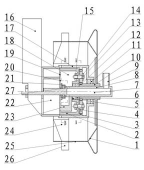
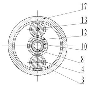
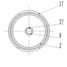
[0011] as attached Figure 1-3 Schematic, the labels in the figure respectively indicate: 1—filming wheel, 2—air cavity, 3—internal gear, 4—air cavity gear, 5—sealing ring, 6—bearing, 7—negative pressure channel, 8—roller Main shaft, 9—negative pressure tube, 10—sleeve (gear bearing seat), 11—bearing, 12—central gear, 13—air chamber gear shaft, 14, 15—nut, 16—kind box, 17—internal tooth bracket , 18—negative pressure chamber, 19—seeding hole, 20—seeding tray, 21—bearing seat, 22—seeding chamber, 23—air-tight block, 24—inoculation box, 25—planting drum, 26—duck beak, 27—negative pressure through hole.

[0012] as attached figure 1 , 2 , 3, the present invention mainly comprises hole sowing cylinder 25, lamination wheel 1, negative pressure seed picker, drum main shaft 8, cooperates by bearing ...


PUM


Abstract

The invention relates to a part on an agricultural seeder, and especially relates to a speed changing air chamber hole seeding apparatus which is suitable for a precise seeder. The apparatus comprises a hole seeding drum, a film pressing roller (1), a negative pressure seed fetching device, and a roller main shaft (8). The negative pressure seed fetching device and the roller main shaft (8) are coupled through a bearing. The negative pressure seed fetching device comprises an air chamber (2) and an air blocking block (23) in the air chamber (2), wherein the air blocking block (23) is fixedly connected with the roller main shaft (8). On a back wall of the air chamber (2), an air chamber gear (4) is connected through an air chamber gear shaft (13). A sleeve pipe (10) is arranged on the roller main shaft (8), wherein the sleeve pipe (10) is slidingly fit or rolling-engaged with the roller main shaft (8). A central gear (12) is arranged on the sleeve pipe (10). The central gear (12) is orderly engaged with the air chamber gear (4) and an inner gear (3) on an inner gear support (17), such that the negative pressure seed fetching device rotates under the driving of the air chamber gear shaft (13). The apparatus provided by the invention is advantaged in that: precise seed discharging is realized through combination of the rotation of the negative pressure chamber and the air blocking of the sliding block. The airtightness of the negative pressure chamber is good, therefore the negative pressure is stable, air leakage of the negative pressure chamber is reduced, seed fetching rate is improved, empty-hole rate is reduced, and seeding speed can be substantially improved.

Description

technical field [0001] The invention relates to a component on an agricultural seeder, in particular to a variable-speed air chamber hole sowing device, which can be used on a precision seeder. technical background [0002] The usual air-suction seed picker (or seed divider) consists of a seed suction disc and a negative pressure chamber. When in use, the seed suction disc is fixed on the end face of the negative pressure chamber through a coupling shaft, and the seed suction disc is a disc. , along the circumferential direction of the edge of the disk, equidistant seed suction holes are evenly distributed. When working, the air is sucked through the suction pipe connected to the negative pressure chamber, and the seed suction disk is driven by the central shaft to rotate on the end face of the negative pressure chamber. The purpose of the rotation of the seed suction disc is to complete two tasks, one is to suck the seeds to the seed suction holes (one or two); The bottom ...

Claims


Application Information

Patent Timeline
Patent Type & Authority Applications(China)
IPC IPC(8): A01C7/04A01C7/20
Inventor 陈恒
Owner 陈恒
Learn More