Film double-sided automatic positioning die-cutting gluing method

An automatic positioning and self-positioning technology, used in chemical instruments and methods, lamination devices, lamination auxiliary operations, etc. Fitting and other problems, to achieve the effect of large size change, reduce the loss of raw materials, and avoid damage

Inactive Publication Date: 2014-07-02
WUHAN UNIV OF TECH
View PDF7 Cites 0 Cited by
  • Summary
  • Abstract
  • Description
  • Claims
  • Application Information

AI Technical Summary

Problems solved by technology

[0004] Document 1 "Laminating machine with alignment lamination function (Patent No.: 200820047317.0)" provides a multi-layer alignment lamination equipment and a control method for eliminating alignment deviation. This method attempts to control the plasticity of the material Deformation is used to achieve alignment, and cannot be used for alignment of adhesive films that do not allow deformation (such as adhesive films for die-cut windows)
[0005] Document 2 "Method for improving the processing technology of multi-layer composite die-cutting products" (CN101186136A) provides a multi-layer composite die-cutting method, in which cursors are printed on the upper and lower layers of laminated materials, and the cursors are tracked after lamination. Die-cutting, using one die-cutting machine to perform two die-cuts, the alignment accuracy of the two films in this process is affected by both the lamination accuracy and the die-cutting accuracy, and it is difficult to achieve high-precision dies with mutual longitudinal positioning relationship cut fit
[0006] Document 3 "Automatic die-cutting machine (Patent No.: 200620012675.9)" provides a rotary die-cutting machine that can realize multi-layer die-cutting and composite functions of films of different materials, but this processing method is still controlled by material Accumulation of plastic deformation to achieve alignment lamination, especially not suitable for multi-layer lamination with large die-cut windows and easy-to-deform application films

Method used


Image

  • Film double-sided automatic positioning die-cutting gluing method

Examples


specific Embodiment approach

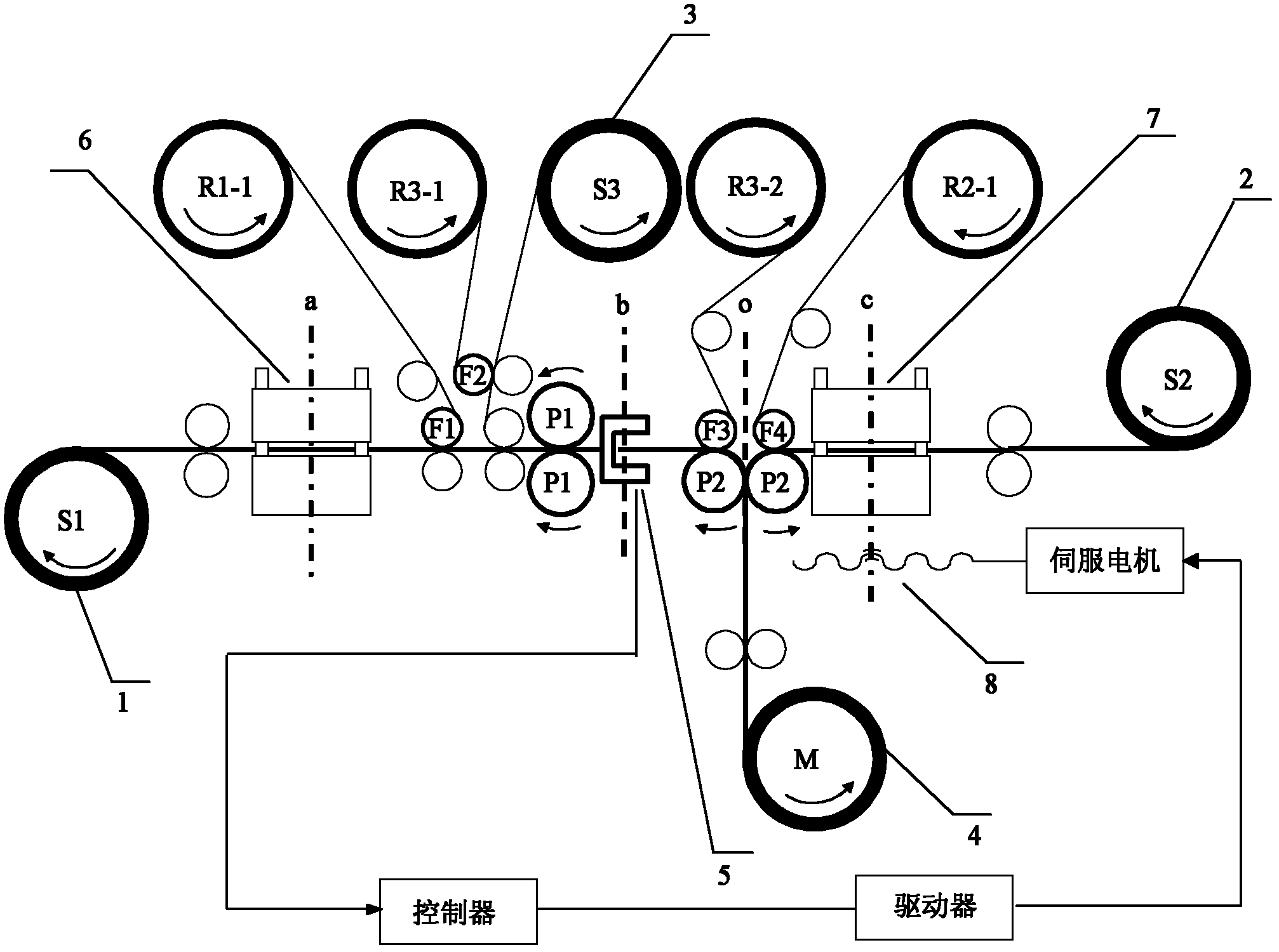
[0055] In this embodiment, according to the process flow of the double-sided self-positioning and laminating method of the film, the specific implementation of the double-sided self-positioning and laminating operation of the film is as follows:

[0056] At one station, the first die-cutting die 6 punches the application film 1, cuts off the upper two layers of the application film 1, and the middle film (ie the application film) is punched into a window. In the figure a is the first The centerline of the punching die. At the position of the color mark sensor 5, there is a window that has been punched at the previous station on the sticking film 1 .

[0057] The color mark sensor 5 detects the displacement between the actual window mark line on the film 1 and the detection reference line b (that is, shifts to the right). The displacement signal is processed by the controller in the control system and sends a control signal to the driver. The servo The motor drives the screw t...


PUM


Abstract

The invention provides a film double-sided automatic positioning die-cutting gluing method, which is used for gluing a first adhesion film (1), a second adhesion film (2) and a substrate film (3) which are provided with double-sided protective films. The method comprises the following steps of: firstly, punching windows on the first adhesion film (1) and the second adhesion film (2); secondly, removing the protective films on the window sides of the first adhesion film (1) and the second adhesion film (2); and finally, gluing to the two sides of the substrate film (3) of which the protective film is removed respectively, and thus obtaining a composite film which uses the substrate film as a middle layer and of which the two sides are provided with the adhesion films having positioning punching windows. Compared with the conventional multilayer film composite molding process method, the method has the advantages of simple process, high positioning die-cutting gluing accuracy, high applicability, capability of realizing continuous processing of multilayer film composite and the like.

Description

technical field [0001] The invention relates to a film die-cutting and bonding method, in particular to a film double-sided automatic positioning die-cutting and bonding method. Background technique [0002] With the rapid development of microelectronics technology and advanced manufacturing technology, the demand for thin film material processing technology is increasing. Usually, the raw material of the film is a single-layer structure with only a certain performance, but in practical applications, it is often necessary to combine two or more layers of films of different materials, that is, in the base film (such as plastic film, cellophane, paper and metal foil) etc.) on top of other film materials (referred to as pasting film), so as to obtain a multi-functional and comprehensive film product. Film compounding is mainly realized by extrusion compounding method and bonding compounding method combined with corresponding equipment. [0003] In some specific application fi...

Claims


Application Information

Patent Timeline
Patent Type & Authority Patents(China)
IPC IPC(8): B32B37/00B32B38/04B32B41/00
Inventor 夏泽中陈静袁佑新肖纯杨坤
Owner WUHAN UNIV OF TECH
Why Eureka
Try Eureka