A multi-purpose single arm portal crane

A crane, multi-purpose technology, applied in the direction of cranes and other directions, can solve problems such as the rationality of the force of the metal structure affecting the crane, the overall stability of the crane, the rise of the center of gravity of the single-arm gantry crane, and the inability to adapt to the crane grab operation. , to achieve the effect of improving dynamic performance and working stability, improving the stability of the whole machine, and increasing the distance

Inactive Publication Date: 2011-12-14
中山市装备制造业科技研究中心 +2
View PDF9 Cites 17 Cited by
  • Summary
  • Abstract
  • Description
  • Claims
  • Application Information

AI Technical Summary

Problems solved by technology

[0002] The single-arm portal crane is a typical loading and unloading equipment for the port's general wharf. The existing single-arm portal crane's jib support point is set on the turntable. In order to meet the lifting height requirements, the turntable and the mechanism set on the turntable must be And the metal structure rises, which leads to the rise of the center of gravity of the single-arm portal crane, which affects the rationality of the metal structure of the crane and the overall stability of the crane
At the same time, the herringbone frame structure of the existing single-arm portal crane also lim

Method used


Image

  • A multi-purpose single arm portal crane
  • A multi-purpose single arm portal crane
  • A multi-purpose single arm portal crane

Examples


Embodiment Construction

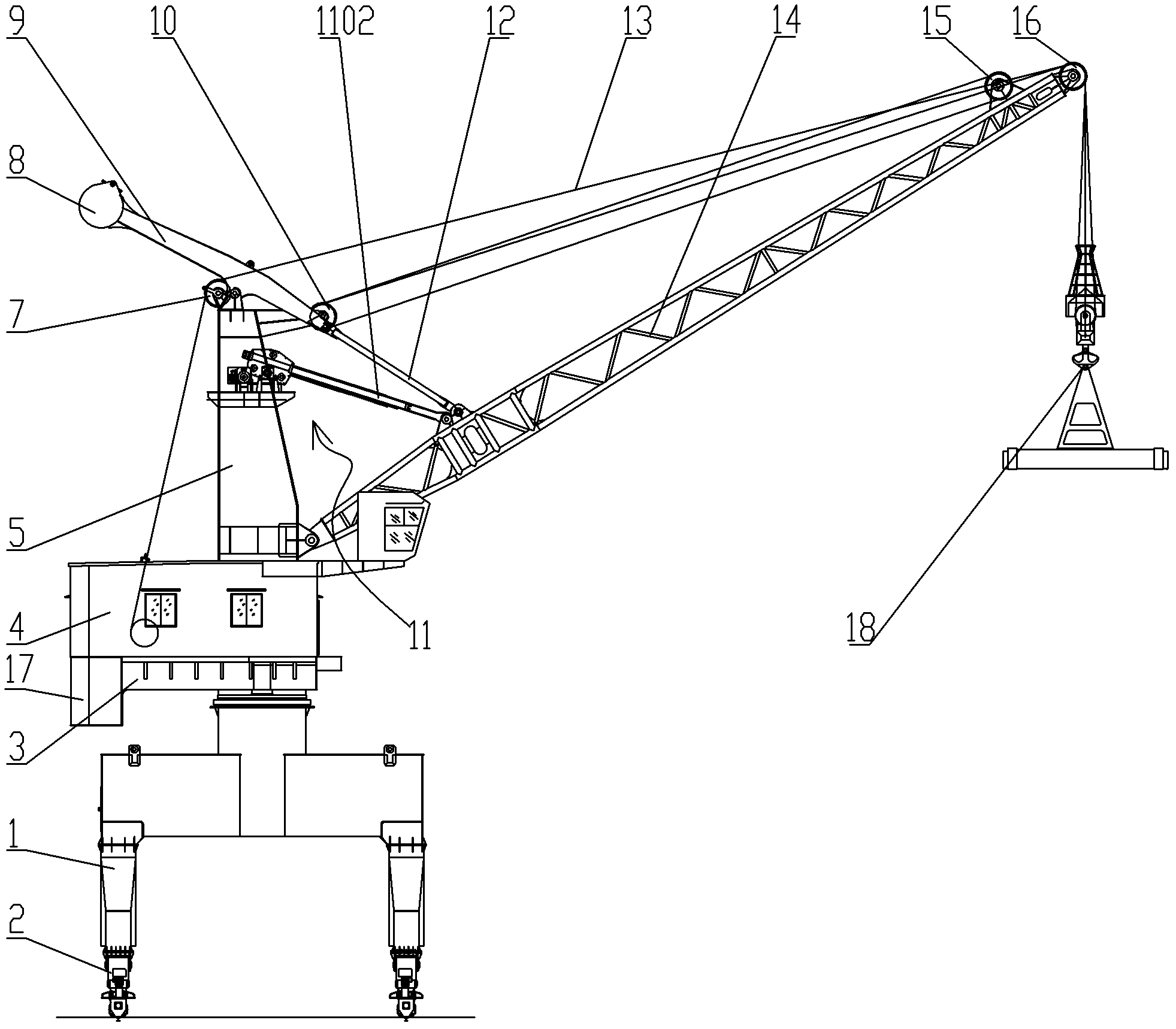
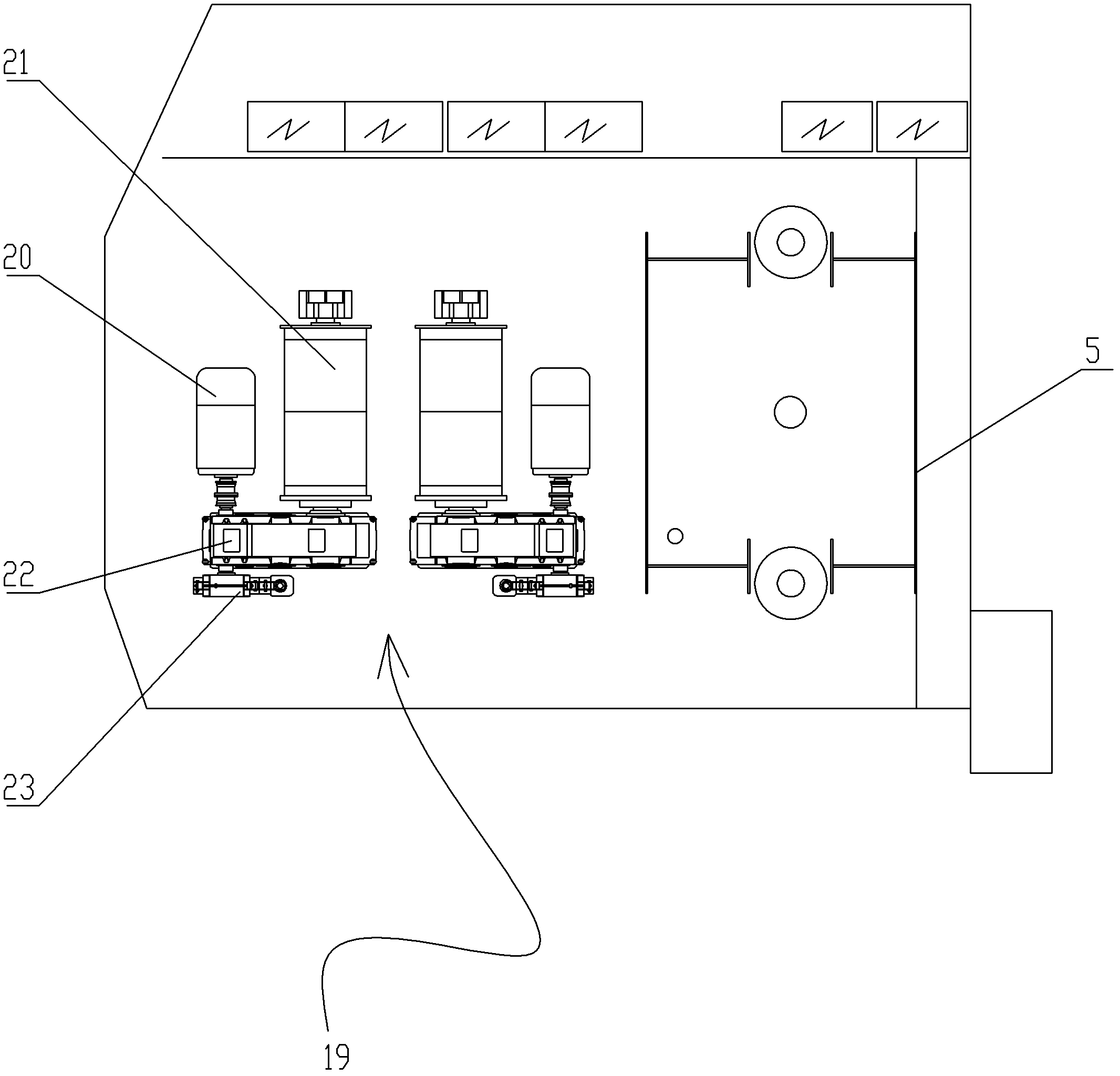
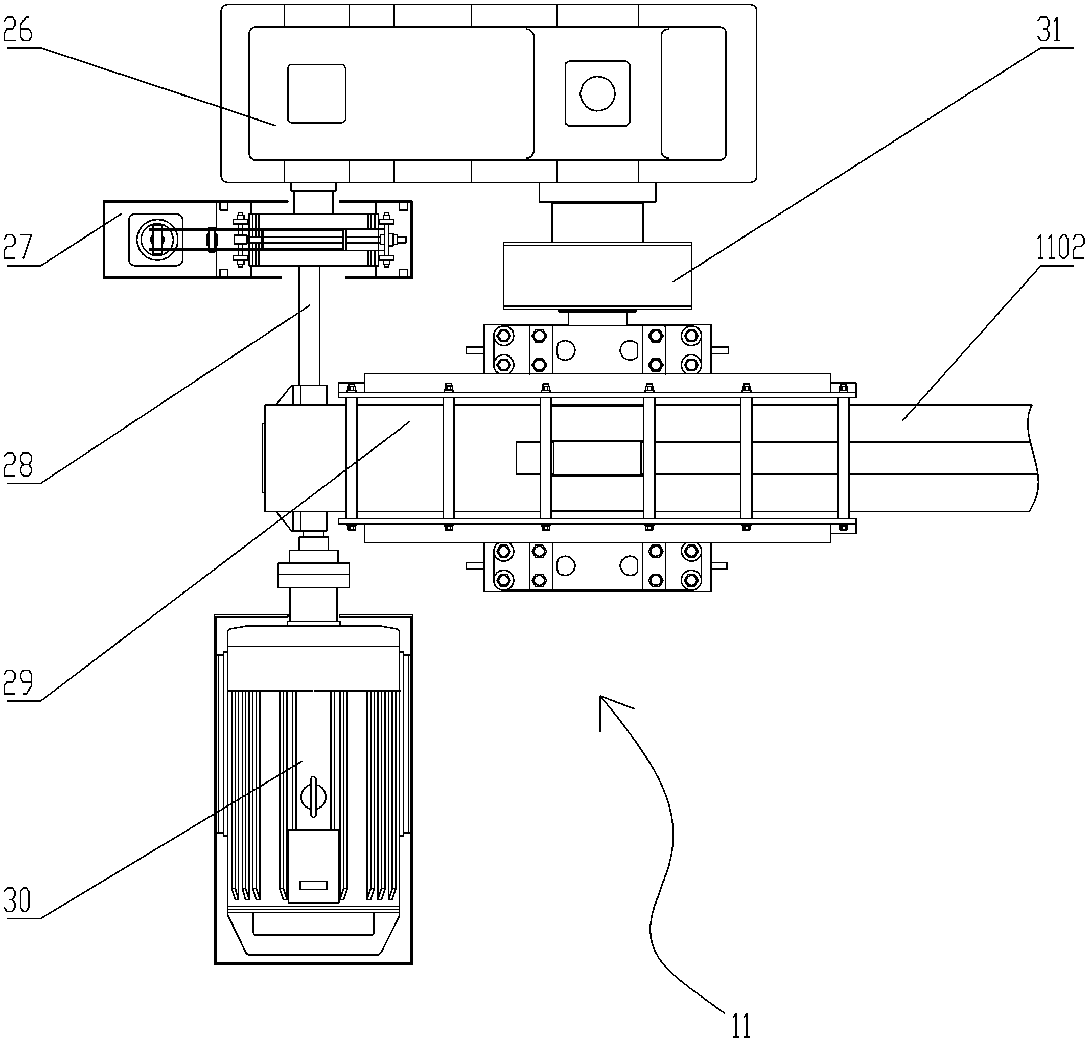
[0021] A multi-purpose single-arm portal crane, comprising a portal frame 1, a running mechanism 2 is provided below the portal frame 1, and a turntable 3 that can rotate relative to the portal frame 1 is provided above the portal frame 1. The rotary table 3. A plate girder column 5 is arranged on the top, and a balance block 20 is provided on the rear side. The lower end of the plate girder column 5 is hinged to the front side with a boom 14, and the front end of the boom 14 is provided with a boom Lifting pulley 16, the upper end of the plate beam type column 5 is provided with a column lifting pulley 7, and a luffing mechanism 11 is provided between the middle part of the plate beam type column 5 and the boom 14. The above-mentioned turntable 3 is provided with a machine room 4, and the above-mentioned lifting driving device 19 is wound with a wire rope 13, and the above-mentioned wire rope 13 goes around the above-mentioned column lifting pulley 7 and the above-mentioned ji...


PUM


Abstract

The invention discloses a multi-purpose single-arm gantry crane, comprising a gantry, a traveling mechanism is arranged below the gantry, and a turntable capable of rotating relative to the gantry is arranged above the gantry. The main points of the technical solution are Yes, there is a plate beam type column above the turntable, a balance block is arranged on the rear side, a lifting arm is hinged on the lower end and the front side of the plate beam type column, and a boom frame is arranged at the front end of the lifting arm. Lifting pulley, the upper end of the plate beam type column is provided with a column lifting pulley, a luffing mechanism is arranged between the middle part of the plate beam type column and the lifting arm, and the turntable is provided with In the machine room, a wire rope is wound around the hoisting drive device, and the wire rope goes around the column hoisting pulley and the boom hoisting pulley in turn and is connected with a hoisting device at the rear end.

Description

【Technical field】 [0001] The invention relates to a working equipment, more specifically a single arm portal crane. 【Background technique】 [0002] The single-arm portal crane is a typical loading and unloading equipment for the port's general wharf. The existing single-arm portal crane's jib support point is set on the turntable. In order to meet the lifting height requirements, the turntable and the mechanism set on the turntable must be With the rise of the metal structure, this leads to the rise of the center of gravity of the single-arm portal crane, which affects the rationality of the metal structure of the crane and the overall stability of the crane. At the same time, the herringbone frame structure of the existing single-arm portal crane also limits the winding of the hoisting wire rope from the hoisting drum to the hoisting pulley block of the herringbone frame to pass through a reverse winding pulley, so that the hoisting wire rope Reverse bending occurs during ...

Claims


Application Information

Patent Timeline
IPC IPC(8): B66C23/16B66C23/78B66C23/76B66C23/82
Inventor 胡吉全林俊宇陈喜崇倪宝君彭永林黄晓晓
Owner 中山市装备制造业科技研究中心
Why Eureka
Try Eureka