Cranes and crane counterweight handling mechanisms, counterweights

A loading and unloading mechanism, crane technology, applied in the direction of the crane, etc., to achieve the effect of facilitating the adjustment of the horizontal attitude and saving the height and space

Inactive Publication Date: 2011-12-14
HUNAN ZOOMLION SPECIAL VEHICLE
View PDF7 Cites 12 Cited by
  • Summary
  • Abstract
  • Description
  • Claims
  • Application Information

AI Technical Summary

Problems solved by technology

[0004] The object of the present invention is to provide a crane to solve the problems caused by the unbalanced load during the lifting and lowering of the counterweight

Method used


Image

  • Cranes and crane counterweight handling mechanisms, counterweights
  • Cranes and crane counterweight handling mechanisms, counterweights
  • Cranes and crane counterweight handling mechanisms, counterweights

Examples


Embodiment Construction

[0035] The embodiments of the present invention will be described in detail below with reference to the accompanying drawings, but the present invention can be implemented in many different ways defined and covered by the claims.

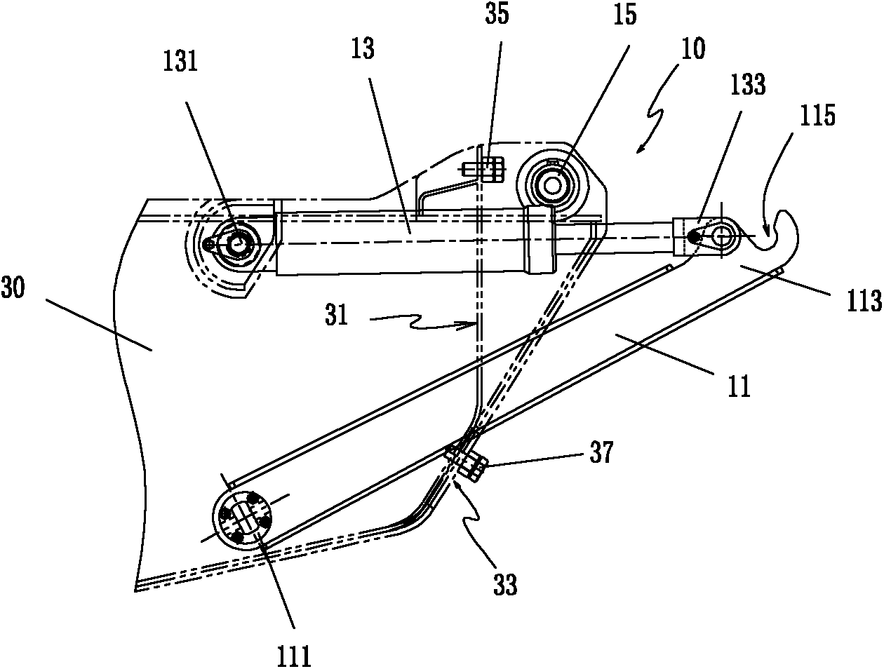
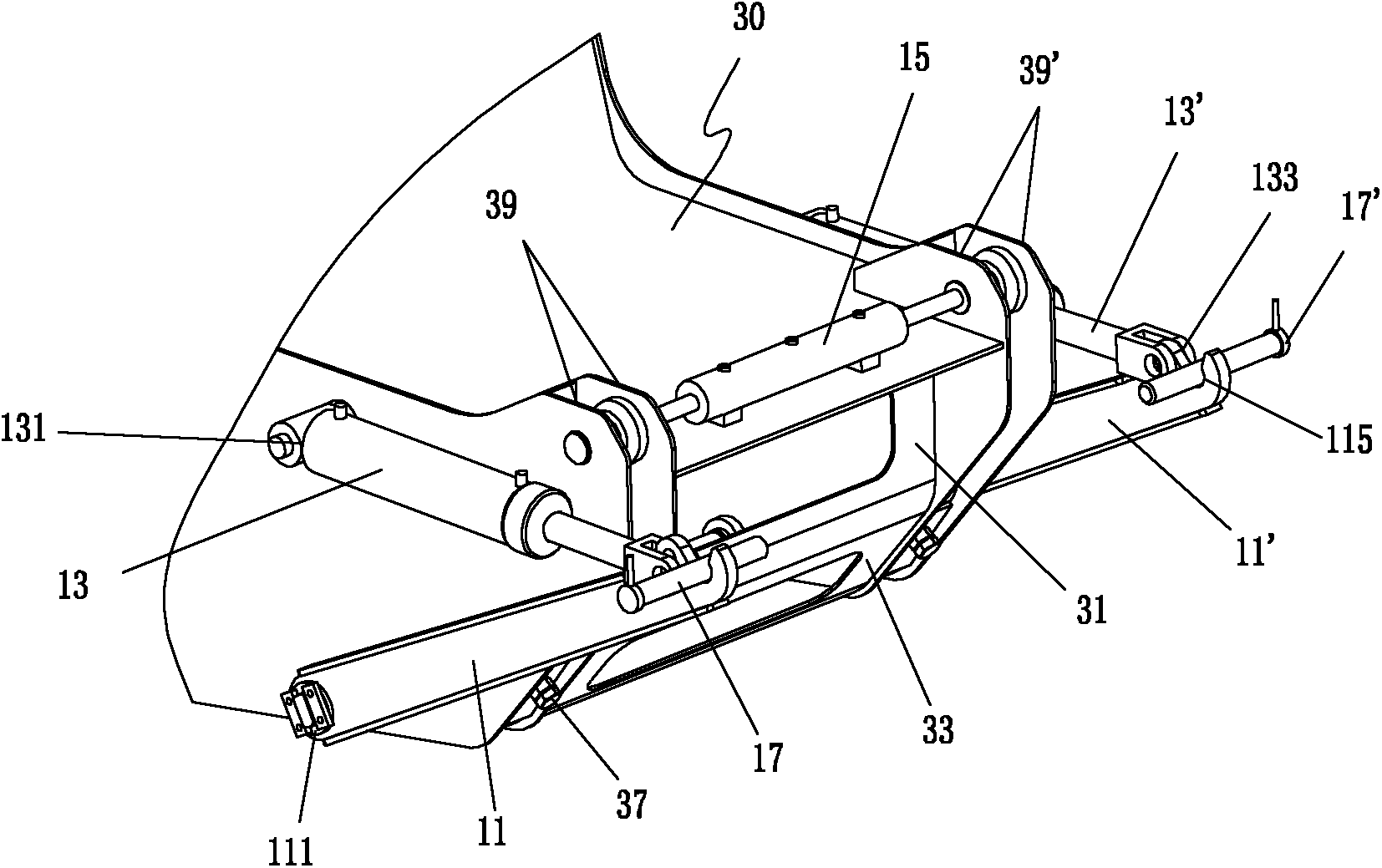
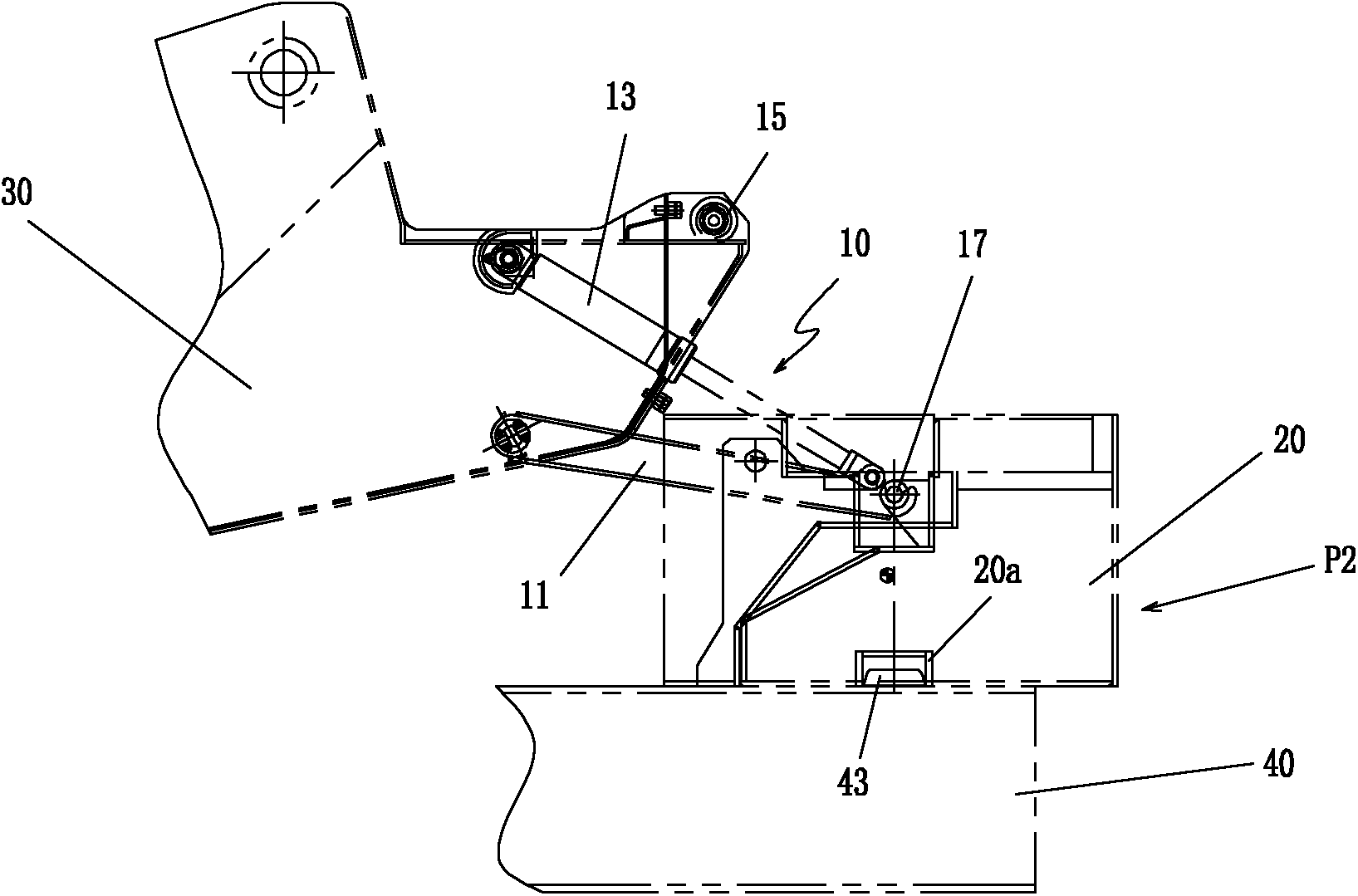
[0036] figure 1 It shows a schematic structural view of the counterweight loading and unloading mechanism of the crane according to the preferred embodiment of the present invention, figure 2 A perspective view showing a counterweight handling mechanism of a crane according to the present invention, image 3 A schematic diagram showing the counterweight of the crane according to the present invention in placement position P2, Figure 4 with Figure 5 A schematic diagram showing the counterweight of the crane according to the present invention in the installation position P1. combined reference Figure 1 to Figure 5 , The counterweight loading and unloading mechanism 10 and the counterweight 20 are installed on the turntable 30 of the crane.

...


PUM


Abstract

Disclosed is a counterweight loading and unloading mechanism for a crane. The counterweight loading and unloading mechanism (10) comprises: two jibs (11, 11'), symmetrically disposed at two sides of a slewing platform (30) of the crane, a first end (111) of each jib being pivotably connected on the slewing platform of the crane, a second end (113) extending outwardly at the tail of the slewing platform and having a latch hook (115); two counterweight cylinders (13, 13'), symmetrically disposed at two sides of the slewing platform of the crane, and driving the jibs to rotate between the installation position (P1) and a placement position (P2) of a counterweight block; and a locking device, disposed at the tail of the slewing platform of the crane and along the width direction of the slewing platform of the crane, the latch hook and the counterweight block being connected detachably through a latch bar, and the latch bar locking and fitting the counterweight block when the counterweight block is at the installation position. Further disclosed are a crane having the counterweight loading and unloading mechanism and a counterweight block fitting the counterweight loading and unloading mechanism. The counterweight loading and unloading mechanism is capable of avoiding offset loading of the cylinder piston rod incurred when the two cylinders are asynchronous, which is very suitable for horizontal arrangement of counterweight cylinders and facilitates the adjustment of horizontal posture of the counterweight block.

Description

technical field [0001] The invention relates to a crane, in particular to a counterweight loading and unloading mechanism and a counterweight block of the crane. Background technique [0002] When the traveling or transporting quality of the crane is limited, but the stability of the crane's hoisting operation requires a large counterweight, a counterweight mechanism that can easily and quickly unload the counterweight is needed. [0003] Chinese patent specification CN201214604Y discloses a counterweight device for a crane, which adopts a combination of fixed counterweight and movable counterweight. The lifting and lowering of the movable counterweight is realized through the expansion and contraction of the lifting cylinder, and the locking and unlocking of the movable counterweight is realized through the locking cylinder. However, the position of the center of gravity of the movable counterweight and the synchronization of the two lifting cylinders are highly required, ...

Claims


Application Information

Patent Timeline
Patent Type & Authority Applications(China)
IPC IPC(8): B66C23/74B66C23/62
CPCB66C23/74
Inventor 钟发忠郭阳春刘荣张建军彭文钦
Owner HUNAN ZOOMLION SPECIAL VEHICLE
Why Eureka
Try Eureka