Cooling device for bearing of two-stage pusher centrifuge and manufacturing method thereof

A technology of cooling device and centrifuge, which is applied in the direction of bearing cooling, bearing components, shafts and bearings, etc., can solve problems such as bearing damage, and achieve the effect of heat reduction and high efficiency

Active Publication Date: 2012-12-26
ZHEJIANG QINGJI CENTRIFUGE MFG
View PDF10 Cites 2 Cited by
  • Summary
  • Abstract
  • Description
  • Claims
  • Application Information

AI Technical Summary

Problems solved by technology

[0004] The purpose of the present invention is to solve the problem that the temperature of the material in the two-stage pusher centrifuge reaches above 100 degrees, and the problem of damage to the bearing caused by the failure to cool down with a single traditional oil cooler is to provide a dual-stage pusher centrifuge bearing with a reasonable structure The cooling device and its manufacturing method, which set a French cooling flange in the bearing seat of the double-stage pusher centrifuge, and use the spiral structure of trapezoidal teeth or rectangular teeth to ensure that the cooling liquid is continuously circulated on the outer layer of the bearing and ensure that the bearing is installed Parts with high strength requirements

Method used


Image

  • Cooling device for bearing of two-stage pusher centrifuge and manufacturing method thereof
  • Cooling device for bearing of two-stage pusher centrifuge and manufacturing method thereof
  • Cooling device for bearing of two-stage pusher centrifuge and manufacturing method thereof

Examples


Embodiment Construction

[0028] The technical solutions of the present invention will be further specifically described below through the embodiments and in conjunction with the accompanying drawings.

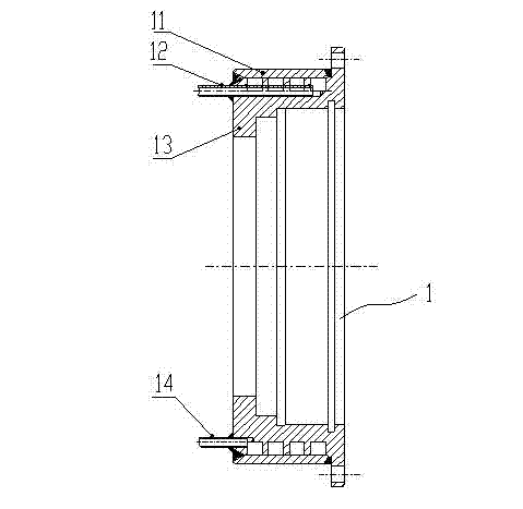
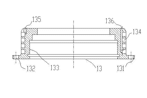
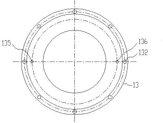
[0029] see figure 1 , the present embodiment is a dual-stage pusher centrifuge bearing cooling device, the solution is to set a cooling flange 1 at the core of the inner hole of the double-stage pusher centrifuge bearing seat, and then introduce the coolant into the cooling flange. The cooling flange 1 includes an outer ring 11 and an inner ring 13, see figure 2 , image 3 , the head end of the inner ring 13 is a flange ring 131, the inner hole of the inner ring 13 is a bearing seat hole 133, and the middle section of the outer surface of the inner ring 13 is processed into a "T"-shaped spiral tooth, which is composed of spiral teeth The spiral groove 134 on the outer cylinder of the inner ring 13, the inner hole of the outer ring 11 and the outer circle of the inner ring 13 provided with the spiral...


PUM


Abstract

The invention relates to the technical field of bearings of centrifuges and specifically relates to a cooling device for bearings of two-stage pusher centrifuges. The objective of the invention is to solve the problem that when temperature of materials in a two-stage pusher centrifuge is over 100 DEG C, a bearing is damaged because mere utilization of the conventional method of oil cooling can not realize drop of temperature. The invention is characterized in that: a cooling flange is provided in the core part of a deep aperture in a bearing pedestal of a two-stage pusher centrifuge; the cooling flange comprises an outer ring and an inner ring; one end of the head of the inner ring is a flange ring; the bore of the inner ring is provided with a bearing pedestal aperture; a helical groove is formed at cylindrical surface of the inner ring through the setting of helical teeth; processing short tube hole and long tube hole respectively communicate with the helical groove; a short copper tube is provided in the short tube hole while a long copper tube is provided in the long tube hole; the bore of the inner ring matches with excircle of the inner ring where the helical groove is provided, and the two are welded into an integrate part. According to the invention, the contact area between a liquid coolant and the inner ring is guaranteed, and the force received by a supporting bearing can be stabilized.

Description

technical field [0001] The invention relates to the technical field of centrifuge bearings, in particular to a bearing cooling device and a manufacturing method of a two-stage pushing material centrifuge. Background technique [0002] In the current two-stage pusher centrifuge, the temperature of the material entering the drum is generally around 50°C, and the temperature of the front bearing of the bearing seat can be reduced by lubricating and cooling the oil circuit. When the temperature of the material reaches 150°C, the cooling of the oil circuit can no longer reduce the excessive temperature of the bearing, which may easily cause damage to the bearing. Most of the existing cooling devices for bearing housings are used to pour coolant into the bearing housing body. Due to the structural complexity of the bearing housing body, its cooling effect and bearing housing strength are affected. For example, the patent publication number is CN 101793293A, a sliding bearing cool...

Claims


Application Information

Patent Timeline
Patent Type & Authority Patents(China)
IPC IPC(8): F16C37/00
Inventor 陶渊卿吕丽珍王刘波余宝华
Owner ZHEJIANG QINGJI CENTRIFUGE MFG
Why Eureka
Try Eureka