Novel friction clutch and separating and combining device thereof

A friction clutch, clutch technology, applied in friction clutches, clutches, mechanical drive clutches, etc., can solve the problems of poor stability, low transmission efficiency, and good heat dissipation of dry multi-plate clutches, and achieve stable clutch function and large transmission torque. , the effect of good heat dissipation

Inactive Publication Date: 2013-05-29
姜成立
View PDF2 Cites 2 Cited by
  • Summary
  • Abstract
  • Description
  • Claims
  • Application Information

AI Technical Summary

Problems solved by technology

[0006] The purpose of the present invention is to provide a friction clutch, which overcomes the disadvantage of low transmission efficiency of the wet multi-plate clutch, solves the problem of poor stability of the dry multi-plate clutch, and has better heat dissipation, and does not rub or wear when it is in the separated state small, good heat dissipation

Method used


Image

  • Novel friction clutch and separating and combining device thereof
  • Novel friction clutch and separating and combining device thereof
  • Novel friction clutch and separating and combining device thereof

Examples


Embodiment 1

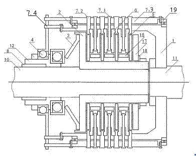
[0028] Friction clutch, the structure of which is as figure 1 with Figure 4 As shown, it includes outer rotor cover 1, inner rotor sleeve 2, release bearing 4, release bearing sliding sleeve 12, fixed bushing 8, inner friction plate 5, outer friction plate 6, thick washer 16, washer 18, inner rotor Disc baffle 17, driving shaft 11, driven shaft 10, diaphragm spring 3 and separation coupling device 7.

[0029] Among them, the inner rotor sleeve 2 is set on the driven shaft 10, and is connected with a key. The inner rotor sleeve 2 is covered with 4 inner friction plates 5, and the inner teeth of the claws on the inner friction plate 5 are connected with the inner rotor sleeve 2. It is connected by spline fit, and there is a thick washer 16 between every two inner friction plates 5, which is used to increase the space distance between the two inner friction plates 5. The outer side of the inner rotor sleeve 2 is covered with an inner rotor baffle plate 17, The outer side of th...

Embodiment 2

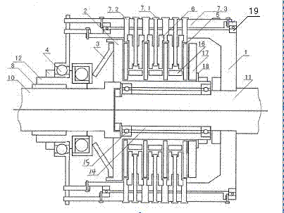
[0034] Friction clutch, the structure of which is as figure 2 with Figure 4 As shown, it includes outer rotor cover 1, inner rotor sleeve 2, release bearing 4, release bearing sliding sleeve 12, fixed bushing 8, inner friction plate 5, outer friction plate 6, thick washer 16, washer 18, inner rotor Disc baffle 17, driving shaft 11, driven shaft 10, diaphragm spring 3 and separation coupling device 7.

[0035] Wherein, the inner moving disk sleeve 2 is set on the thinner end of the driving shaft 11, two small bearings 15 are installed at both ends of the inner hole of the inner moving disk sleeve 2, and a bushing 14 is arranged between the two small bearings 15, and the inner moving disk The disc sleeve 2 is connected with the driven shaft 10 by a spline fit, and the inner drive disc sleeve 2 is covered with 4 inner friction plates 5, and the inner teeth of the protruding claws on the inner friction plates 5 are connected with the inner drive disc sleeve 2 by a spline fit. ...

Embodiment 3

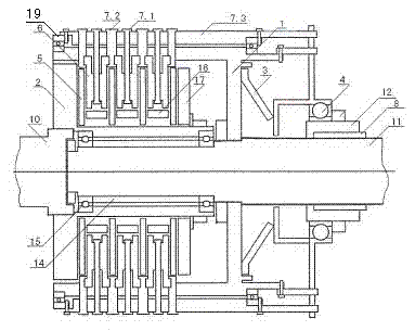
[0038] Friction clutch, the structure of which is as image 3 with Figure 4 As shown, it includes outer rotor cover 1, inner rotor sleeve 2, release bearing 4, release bearing sliding sleeve 12, fixed bushing 8, inner friction plate 5, outer friction plate 6, thick washer 16, washer 18, inner rotor Disc baffle 17, driving shaft 11, driven shaft 10, diaphragm spring 3 and separation coupling device 7.

[0039] Wherein, the inner moving disk sleeve 2 is set on the thinner end of the driving shaft 11, two small bearings 15 are installed at both ends of the inner hole of the inner moving disk sleeve 2, and a bushing 14 is arranged between the two small bearings 15, and the inner moving disk The disc sleeve 2 is connected with the driven shaft 10 by a spline fit, and the inner drive disc sleeve 2 is covered with 4 inner friction plates 5, and the inner teeth of the protruding claws on the inner friction plates 5 are connected with the inner drive disc sleeve 2 by a spline fit. T...


PUM


Abstract

The invention provides a novel friction clutch. The friction clutch provided by the invention mainly comprises an outer driving disk cover, an inner driving disk sleeve, a release bearing, internal friction pieces, an external friction piece, a driving shaft and a driven shaft, wherein the outer driving disk cover is connected with the driving shaft; the release bearing bell is sleeved on the outside of a sliding sleeve, the sliding sleeve is sleeved outside a lining, the sliding sleeve and the lining are sleeved on the driving shaft or the driven shaft; the external friction piece is connected with the outer driving disk cover and positioned between two internal friction pieces, and a thick washer is arranged between the two adjacent internal friction pieces. The friction clutch is characterized in that the release bearing is connected with a separating and combining device which mainly comprises a combining mechanism, a separating mechanism, and a permanent connecting mechanism, wherein the combining mechanism and the separating mechanism are respectively connected with the permanent connecting mechanism. The clutch provided by the invention has the advantages of stable on-off function, large transmission torque, small abrasion, high transmission efficiency, good heat dispersion, low failure rate and small radial space; when the clutch is used on a motorcycle, the existing manual control system or pedal operating system can be utilized, thereby completing the functions of combination and separation.

Description

technical field [0001] The invention relates to the design of a motor vehicle clutch, and in particular provides a friction clutch and a separating and combining device thereof. Background technique [0002] The existing clutch usually adopts the oil bath multi-plate type. When the clutch is in the disengaged state, the separation gap between the inner friction plate and the outer friction plate is too small, and the viscous effect of the lubricating oil causes a large frictional resistance when slipping. The transmission efficiency is low; and the stability of the dry double-plate clutch is poor. When it is in the disengaged state, it is prone to friction, large wear, and poor heat dissipation. [0003] When the motorcycle uses a wet multi-disc clutch, the cycle gear motorcycle has a certain fuel-saving effect, but the safety is poor. When the speed is fast, the phenomenon of shifting from neutral gear to first gear often occurs, and it is very dangerous to damage the gear....

Claims


Application Information

Patent Timeline
Patent Type & Authority Patents(China)
IPC IPC(8): F16D13/60F16D13/40F16D13/52
Inventor 姜成立
Owner 姜成立
Why Eureka
Try Eureka