vehicle transmission

A transmission and transmission oil technology, applied in the direction of couplings, clutches, fluid-driven clutches, etc., can solve problems such as complex shifting processes

Active Publication Date: 2016-08-03
ZF FRIEDRICHSHAFEN AG
View PDF4 Cites 0 Cited by
  • Summary
  • Abstract
  • Description
  • Claims
  • Application Information

AI Technical Summary

Problems solved by technology

However, the high-grade position and the structure of the multi-group transmission also cause complicated shifting process

Method used


Image

  • vehicle transmission

Examples


Embodiment Construction

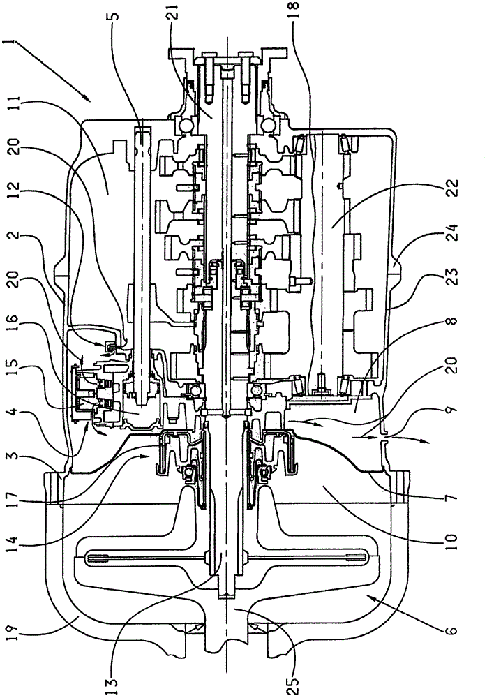
[0020] The vehicle transmission 1 shown comprises a transmission housing 2 which in this example is assembled from two housing parts, namely a drive-side housing half 23 and a rear output-side housing half 24 . On the drive side, the drive-side housing half shell 23 merges into the clutch bell 3 , wherein the clutch bell 3 is embodied in one piece with the drive-side housing half 23 . In a next step, the clutch housing 19 is connected to the clutch bell 3 on the drive side. The clutch housing 19 is screwed, for example, to the clutch bell 3 . Arranged in the clutch housing 19 are the basic components of the starter clutch 6 embodied as a multi-disk clutch.

[0021] The starter clutch 6 can be driven on the drive side via a drive shaft 25 by a drive motor (not shown). The drive torque is conducted via the transmission input shaft 13 into the vehicle transmission 1 by the starter clutch 6 . In the vehicle transmission 1 , the drive torque is directed to the transmission outpu...


PUM


Abstract

A vehicle transmission (1) having a clutch bell (3) arranged on the drive side at a transmission housing (2) and a shift element (5) for actuating the vehicle transmission (1) and / or the pneumatic assembly (4) of the starter clutch (6). A partition wall (7) is arranged in the clutch bell (3) which forms an exhaust chamber (8) in the interior of the clutch bell (3) on the transmission side of the partition wall (7) , wherein at least one outlet opening (9) is provided at the clutch bell (3) which connects the exhaust chamber (8) to the surrounding environment, and wherein the pneumatic assembly (4) is in the following manner Arranged in the transmission housing (2), ie, so that the exhaust gas of the pneumatic assembly (4) can flow into the surrounding environment through the exhaust chamber (8) and the outlet opening (9).

Description

technical field [0001] The invention relates to a vehicle transmission. Background technique [0002] In particular, transmissions in drive trains of commercial vehicles often have a high number of gear stages. To achieve such a high number of gears, multi-group transmissions have proven to be advantageous. However, the high-grade positions and the structure of the multi-group speed changer also cause complicated shifting processes. Such multi-group transmissions are therefore generally designed as automatic transmissions in order to achieve a comfortable and safe driving for the driver despite complex shifting operations. In automatic transmissions, the various shifts are brought about, for example, by means of pneumatically actuated shifting devices. The shifting device is generally a pneumatic piston-cylinder unit, which is supplied with compressed gas via electronically actuatable pneumatic valves. Further elements of the automatic vehicle transmission control are va...

Claims


Application Information

Patent Timeline
Patent Type & Authority Patents(China)
IPC IPC(8): F16H57/027F16H63/30F16D25/08F16D25/12
CPCF16H57/027F16D25/083F16D25/123F16D2300/26F16H63/3023
Inventor 格哈德·霍林
Owner ZF FRIEDRICHSHAFEN AG
Why Eureka
Try Eureka