Plate heat exchanger
A plate heat exchanger and plate technology, applied in the design of plate heat exchangers and the field of plate heat exchangers, can solve the problems of increasing heat exchange units of heat exchangers, unsatisfactory heat exchange effects, and large heat exchangers, etc. Improve heat exchange area, compact structure and small volume
- Summary
- Abstract
- Description
- Claims
- Application Information
AI Technical Summary
Problems solved by technology
Method used
Image

Examples
Embodiment Construction
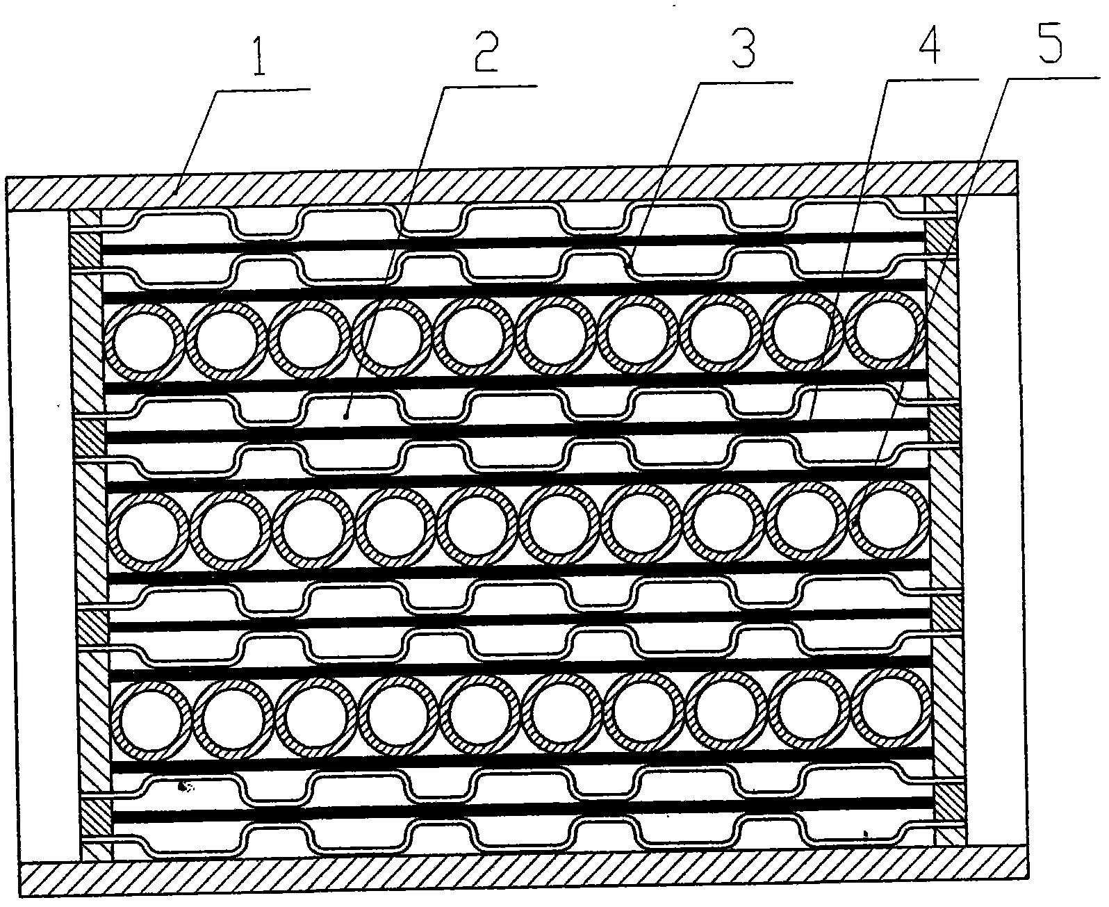
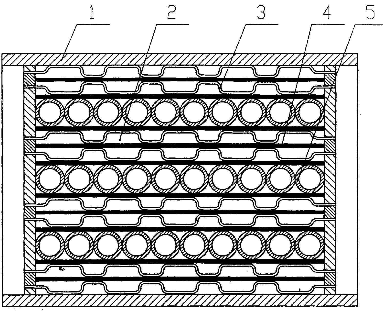
[0007] For a better understanding of the present invention, it will be further described in detail below in conjunction with the accompanying drawings and embodiments.
[0008] Such as figure 1 As shown, the plate heat exchanger of the present invention is mainly composed of a shell 1, a plate core 2 placed in the shell, and a medium inlet and outlet arranged on the shell or the core. The plate core 2 is composed of It is assembled by several unit bodies stacked by heat exchange plates 3. The unit body and the unit body and the unit body are all medium circulation channels, and one or more layers of conductive metal plates are installed in the medium circulation channel. 4. There is a support body 5 between the plates of the multi-layer conductive metal plate; the conductive metal plate 4 used can be a flat plate, or a metal corrugated plate with corrugations, which greatly increases the heat exchange of the circulating medium Small area, high heat replacement rate, improved ...
PUM
 Abstract
Description
Claims
Application Information