Tangential fretting test device and its test method

A test device and testing machine technology, which is applied in the direction of applying repetitive force/pulsation force to test the strength of materials, test wear resistance, etc., can solve problems such as economic loss and shorten the life of parts, and achieve the effect of simple operation

Inactive Publication Date: 2011-12-14
XI AN JIAOTONG UNIV
View PDF7 Cites 33 Cited by
  • Summary
  • Abstract
  • Description
  • Claims
  • Application Information

AI Technical Summary

Problems solved by technology

Tangential fretting greatly shortens the li...

Method used


Image

  • Tangential fretting test device and its test method
  • Tangential fretting test device and its test method
  • Tangential fretting test device and its test method

Examples


Embodiment 1

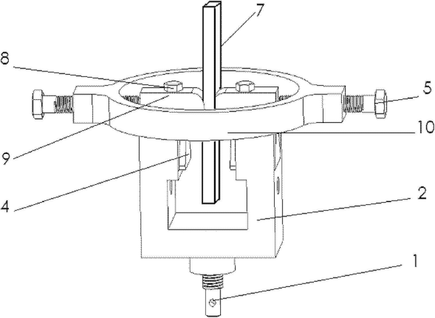
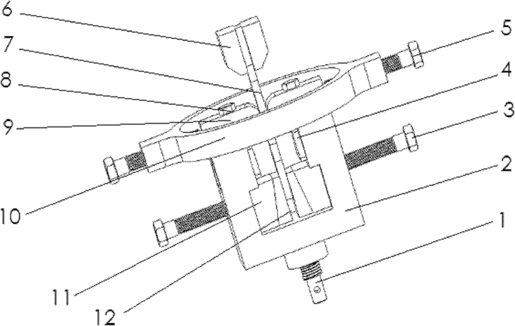
[0024] Such as figure 2 As shown, in the device for realizing the fretting fatigue test, the locking part includes the first pair of wedge blocks 11 and the second pair of wedge blocks 12 placed in the U-shaped holder 2, and the two sides of the U-shaped holder are symmetrically provided with screws. The screw hole is connected with a locking bolt 3, and the end of the locking bolt extends into the U-shaped clamping seat to apply a clamping force to the first pair of wedges, and then the first pair of wedges clamps the second pair of wedges. The second pair of wedge blocks finally locks the lower end of the test piece 7; the purpose of designing two pairs of wedge blocks 11 and 12 is to make the test piece 7 tighter and tighter without axial displacement. The cylindrical contact indenter 9 is connected with the dovetail block 4 through the connecting bolt 8, and slides along the dovetail groove, and the lower chuck 1 of the U-shaped clamp 2 is connected with the testing machi...

Embodiment 2

[0031] Such as Figure 4 , Figure 5 As shown, in the fretting wear experimental device, the pre-tension member 19 includes a tension force measuring ring 16 vertically placed in the pressure force measuring ring 10 and the U-shaped holder 2, and the tension force measuring ring is provided with clamps respectively. Hold the upper and lower two specimen clamps 20 (connected by pins 18) on the upper and lower ends of the specimen 7. The upper specimen clamp is connected with the upper chuck of the testing machine through the upper connector 17 on the upper end of the tension measuring ring. The clamp is connected to the lower connecting piece 13 at the lower end of the tensile force measuring ring, and the pretensioning force is applied to the test piece 7 by tightening the pretension nut 14 on the lower connecting piece 13, and the ring body at the lower end of the force measuring ring is provided with a set bolt 15 The lower connecting piece is locked to ensure that the conn...


PUM


Abstract

The invention discloses a tangential fretting test device and a test method thereof, and is characterized in that a load-controlled fretting fatigue test and a displacement-controlled fretting wear test can respectively be realized through different clamp combinations, thus generating a new detection method for material friction performance. Contact matching parts (contact pressure heads and testpiece) are in a line/plane type of contact, wherein, plane/plane contact and ball/plane contact can be realized respectively by replacing different contact pressure heads. The contact pressure heads are in connection with dovetail blocks in dovetail grooves and are slidable in the dovetail grooves, thus playing a positioning role. A pressure proving ring functions as a spring, so that detachment of the contact matching parts can be avoided and exertion of normal pressure can be guaranteed. And the pretension force and normal pressure are respectively obtained through a tension proving ring and the pressure proving ring, while the cyclic axial stress and cyclic displacement are set by a computer, thus finishing the fretting fatigue and the fretting wear tests respectively. The device and method of the invention are mainly used for tangential fretting tests.

Description

technical field [0001] The invention relates to a test device and a test method for evaluating the friction and wear performance and fretting fatigue life of materials or composite materials. Background technique [0002] Fretting damage has long been recognized as premature fatigue failure in mechanical components due to wear. Fretting damage may occur at the joint between contact parts, which bears tiny cyclic sliding displacement, and the sliding amplitude is very small, generally in the order of microns (<300μm), and the contact load can be applied to one or two contact parts External vibration and fatigue stress are generated. Usually, fretting can be divided into two forms: fretting wear and fretting fatigue by judging whether the contact load is generated by vibration or fatigue stress. Fretting wear and fretting fatigue are easily confused. Dynamic wear is a wear problem, which is mainly manifested as the loss of material; and fretting fatigue is a fatigue proble...

Claims


Application Information

Patent Timeline
IPC IPC(8): G01N3/56G01N3/32
Inventor 方钦志孙斌钱炯
Owner XI AN JIAOTONG UNIV
Why Eureka
Try Eureka