
Displacement amplification type magnetostriction energy converter

A technology of magnetostriction and displacement amplification, which is applied in the direction of vibrating fluid, etc., can solve the problems of weak radiation and low transducer power, and achieve the effects of high efficiency, low stiffness and reduced resonance frequency

Pending Publication Date: 2020-09-15
HUNAN UNIV
View PDF0 Cites 0 Cited by
  • Summary
  • Abstract
  • Description
  • Claims
  • Application Information

AI Technical Summary

Problems solved by technology

[0004] The problem to be solved by the present invention is to provide a displacement amplified magnetostrictive transducer for the problems of low power and weak radiation of traditional transducers

Method used


Image

  • Displacement amplification type magnetostriction energy converter
  • Displacement amplification type magnetostriction energy converter
  • Displacement amplification type magnetostriction energy converter

Examples


Embodiment 1

[0055] The invention provides a low-frequency high-power giant magnetostrictive electroacoustic transducer.

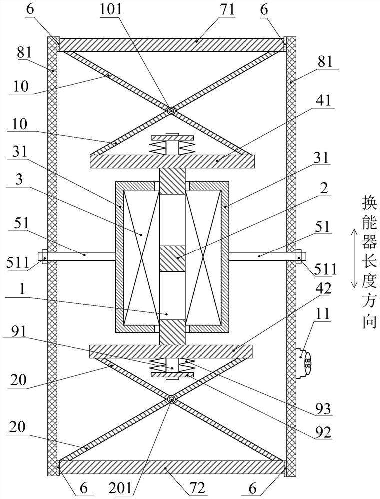
[0056] Such as figure 1 As shown, the present invention provides a displacement amplified magnetostrictive transducer, which includes a transducer housing with a closed inner cavity, a magnetostrictive structure extending in the length direction of the transducer, and a magnetostrictive structure wound around the magnetic The drive coil 3 on the stretchable structure, the magnetostrictive structure and the drive coil 3 are both arranged in the closed inner cavity.

[0057] A drive structure, a vibrator structure, and a displacement amplification mechanism are arranged inside the transducer housing.

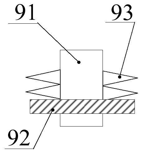
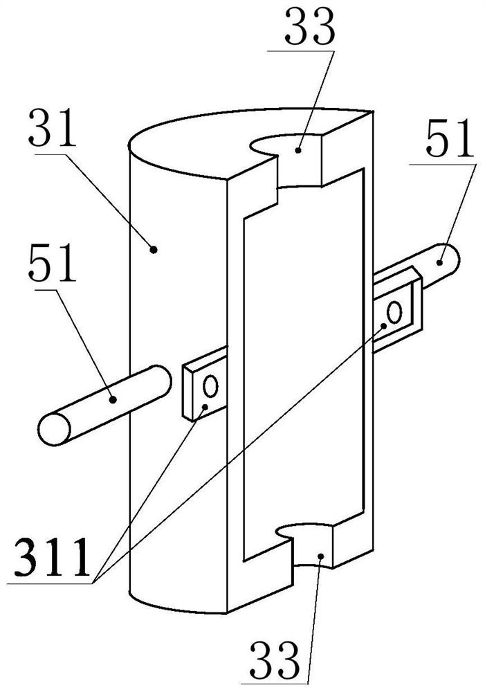
[0058] In this embodiment, the transducer may include a magnetostrictive body 1 (that is, a vibrator), a permanent magnet 2, a drive coil 3, a first connecting plate 41, a second connecting plate 42, a first / second scissor structure, First radiation surface 71, second ra...

Embodiment 2

[0094] Compared with Embodiment 1, the transducer housing in this embodiment can adopt a bellows housing. The transducer housing can completely adopt a bellows structure, or, as shown in this embodiment, a combination of a bellows structure and a rigid structure. Use a bellows with less rigidity as the shell to reduce the resonant frequency of the transducer, and when the bellows shell of the transducer is subjected to water pressure, the bellows will be elastically deformed, and the pressure will be transmitted to the internal gas, and the energy will be converted. The internal pressure of the transducer is equal to the external hydrostatic pressure, thereby increasing the working water depth of the transducer, realizing the low-frequency high-power transmission of the transducer working in deep sea, and reducing the overall assembly quality of the transducer, with small size and light weight , low frequency, high power and high efficiency. The remainder of this embodiment i...

Embodiment 3

[0103] The difference between Embodiment 3 and Embodiments 1 and 2 is that the closed cavity is also filled with pressure compensation gas or pressure compensation liquid. The pressure compensating gas or liquid can further increase the working water depth of the transducer, and the rest of this embodiment is the same as Embodiments 1 and 2. The pressure compensation filling liquid can be any one of castor oil, silicone oil and transformer oil. The pressure compensation filling liquid can be injected into the interior of the transducer housing through a liquid filling hole (not shown in the figure).


PUM


Abstract

The invention provides a displacement amplification type magnetostriction energy converter. An energy converter shell, a magnetostriction structure and a drive coil are included. The energy convertershell comprises a barrel, a first radiating face and a second radiating face. The first radiating face and the second radiating face are connected with the barrel through elastic seal materials. One end and the other end of the magnetostriction structure are fixedly connected with a first connecting plate and a second connecting plate correspondingly. The two end portions of one side of a first shear fork type structure and the two end portions of the other side of the first shear fork type structure are correspondingly hinged to the first connecting plate and the first radiating face. The twoend portions of one side of a second shear fork type structure and the two end portions of the other side of the second shear fork type structure are correspondingly hinged to the second connecting plate and the second radiating face. When current is led to the drive coil, the magnetostriction structure vibrates in the length direction of the energy converter, the first shear fork type structureand the second shear fork type structure stretch and contract in the length direction of the energy converter, and accordingly the first radiating face and the second radiating face vibrate in the length direction of the energy converter.

Description

technical field [0001] The invention relates to a displacement amplifying magnetostrictive transducer, in particular to a low-frequency and high-power giant magnetostrictive electroacoustic transducer for ocean detection. Background technique [0002] So far, sound waves are the only energy carrier known to man that can travel long distances in the ocean. As an electro-acoustic transducer capable of emitting sound waves, it has very important application value whether it is in the civilian field, such as marine geomorphology detection, seabed resource development, etc., or in the military field, such as underwater target detection, underwater acoustic communication, etc. . [0003] As a mechanical wave, sound waves have a small attenuation of energy transmitted in water (the attenuation rate is one thousandth of that of electromagnetic waves), and the transmission distance is long, and the lower the frequency of the sound wave, the smaller the energy loss caused by the abso...

Claims


Application Information

Patent Timeline
Patent Type & Authority Applications(China)
IPC IPC(8): B06B1/08
CPCB06B1/08B06B2201/74
Inventor 杨鑫杨明智罗安欧阳晓平
Owner HUNAN UNIV
Learn More