A color image forming method
A technology of color image and stereoscopic image, applied to color luminous image with grayscale change effect, stereoscopic, forming a dynamic field, which can solve the problems of unrealizable lighting method, simple text or graphics, etc.
- Summary
- Abstract
- Description
- Claims
- Application Information
AI Technical Summary
Problems solved by technology
Method used
Image
Examples
Embodiment approach 1
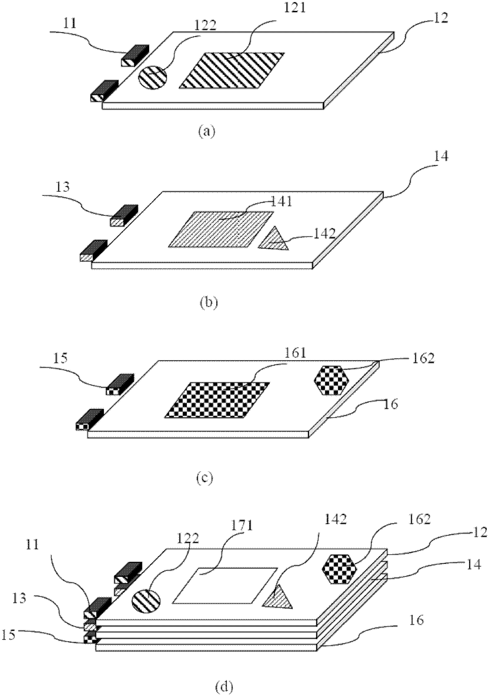
[0034] The first embodiment takes forming a static color image as an example to introduce the working principle of the color image forming method of the present invention. For ease of understanding, firstly, a brief introduction is made to the light emitting device involved in the method of the present invention. see figure 1 , figure 1 It is a light emitting device related to the color image forming method according to the first embodiment of the present invention. As shown in the figure, the light-emitting device includes three light guide films, and each light guide film is provided with a corresponding light source device, which are respectively a light guide film 12 and a light source device 11 on one side thereof, and a light guide film 14. And the light source device 13 and the light guide film 16 on one side thereof and the light source device 15 on one side thereof.
[0035] figure 1 (a) shows the light guide film 12 and the light source device 11 . The material ...
no. 2 approach
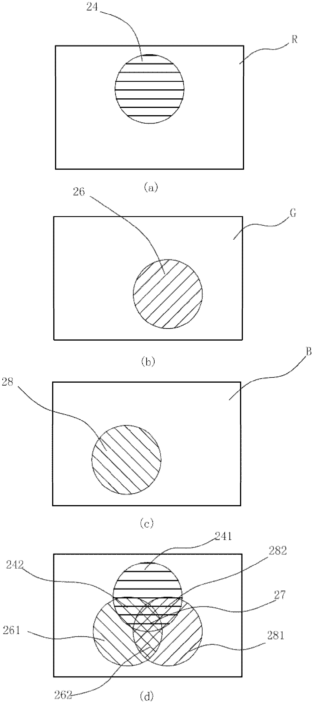
[0055] See Figure 6 , Figure 6 It is a light emitting device according to a color image forming method according to a second embodiment of the present invention. Such as Figure 6 As shown, this embodiment takes the simplest light-guiding image with only three colors of R, G, and B as an example to illustrate the method for forming a dynamic color light-emitting image. Figure 6 (a) is the light guide image on the red light guide film, Figure 6 (b) is the light guide image on the green light guide film, Figure 6 (c) is the light guide image on the blue light guide film; three layers of light guide images are combined to form Figure 6 Color image shown in (d). Controlled by an external circuit (not shown in the figure) Figure 6 In (a), 6(b), and 6(c), the R, G, and B three-color light source devices used to emit light undergo the following changes: when they are turned on individually in turn, red, green, and blue images can be obtained in sequence Light; or turn o...
no. 3 approach
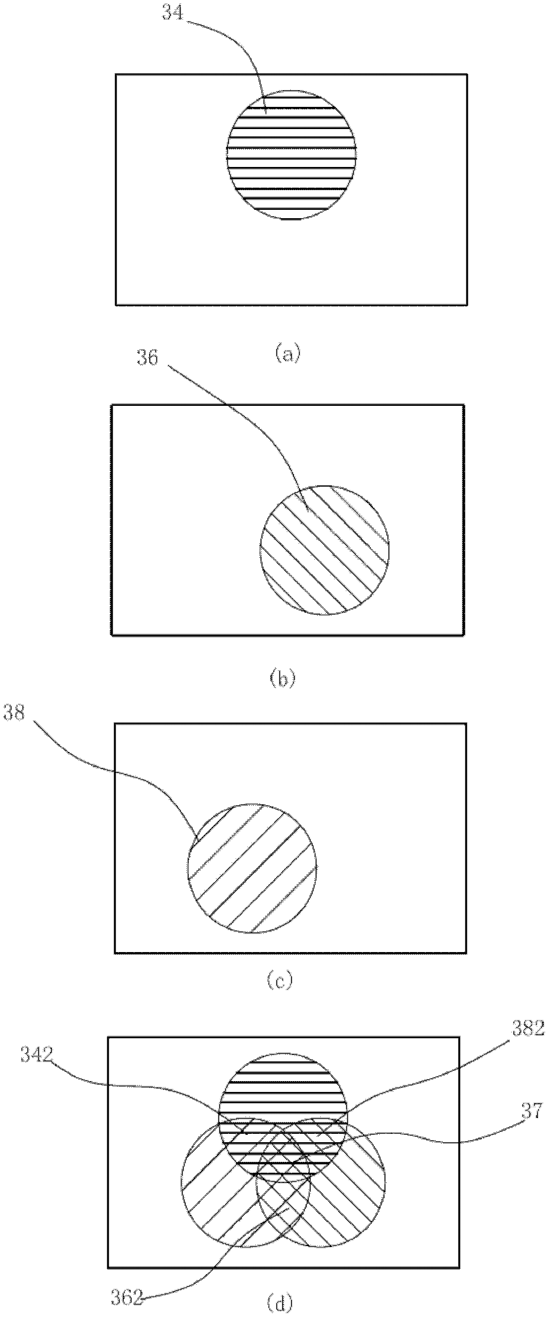
[0057] See Figure 7 , Figure 7 It is a light emitting device related to a color image forming method according to a third embodiment of the present invention. Such as Figure 7 As shown, this embodiment uses three-layer images as an example to describe the formation method of continuous dynamic light-emitting images. Figures (a), 7(b), and 7(c) are illuminated by side-light LEDs, and each single-layer image has the same graphics Composed, but the angle of the graphics is different, Figure 7 (b) for Figure 7 (a) Rotate 22.5 degrees clockwise, Figure 7 (c) for Figure 7(a) Rotate 22.5 degrees counterclockwise. Continuous dynamic lighting images can be obtained by controlling the lighting timing of the LEDs illuminated by the three-layer image. The LEDs of the three-layer image lighting in this embodiment can be the same color or different colors.
[0058] In the above three embodiments, no matter it is used to form a static color image or a dynamic color image, the ...
PUM
| Property | Measurement | Unit |
|---|---|---|
| Thickness | aaaaa | aaaaa |
| Thickness | aaaaa | aaaaa |
Abstract
Description
Claims
Application Information
 - R&D
- Intellectual Property
- Life Sciences
- Materials
- Tech Scout
- Unparalleled Data Quality
- Higher Quality Content
- 60% Fewer Hallucinations
Browse by: Latest US Patents, China's latest patents, Technical Efficacy Thesaurus, Application Domain, Technology Topic, Popular Technical Reports.
© 2025 PatSnap. All rights reserved.Legal|Privacy policy|Modern Slavery Act Transparency Statement|Sitemap|About US| Contact US: help@patsnap.com


