
A casing for a battery pack

A technology for battery packs and housings, which is applied to battery pack parts, circuits, electrical components, etc., which can solve the problems of high maintenance costs, increased costs, and reduced space for vehicles, and achieves a wide application and convenient series-parallel connection Effect

Inactive Publication Date: 2011-12-14
深圳市益佳通科技股份有限公司
View PDF5 Cites 12 Cited by
  • Summary
  • Abstract
  • Description
  • Claims
  • Application Information

AI Technical Summary

Problems solved by technology

This design method is only to arrange a plurality of batteries in a battery case to arrange the batteries, which is applicable to some situations, but for the growing electric vehicle industry, a battery pack case often cannot meet the power demand. Multiple shells will be used to set up multiple rows of batteries for common use
[0003] In this case, the battery packs are placed separately according to the space of the electric vehicle, and then electrically connected. Although this can meet the needs of different places, the random placement of the battery packs will bring inconvenience to the circuit connection and cause Reduced and messy vehicle use space
[0004] Patent application 201010264041.3 proposes a new structure of a battery pack. In this structure, a battery block that arranges a plurality of rechargeable batteries at predetermined positions through a battery holder is accommodated in the battery case. A plurality of battery blocks are accommodated at predetermined intervals, and a hollow partition wall having a hollow interior and opening the hollow portion on the surface of the battery case is provided between adjacent battery blocks, and the hollow partition walls are arranged in a thermally coupled state. As for the battery block, although a plurality of battery packs can be arranged in the above-mentioned design method of the battery pack, its main purpose is to dissipate heat from the battery, and the shells of the battery packs are not considered, so for different battery packs The battery case of the block is fixedly connected. The fixed connection method makes the battery pack unable to be configured according to the actual situation. It can only be set according to the fixed mode. When additional power is required or the battery pack is replaced. , it is impossible to simply increase the power, and the original power battery pack needs to be replaced, which increases the cost. If the battery pack needs to be maintained, the entire battery pack must be disassembled, and the maintenance cost is high

Method used


Image

  • A casing for a battery pack
  • A casing for a battery pack
  • A casing for a battery pack

Examples


Embodiment Construction

[0027] Below, the implementation of the present invention will be described in detail in conjunction with the accompanying drawings.

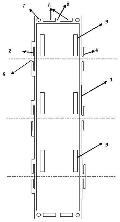
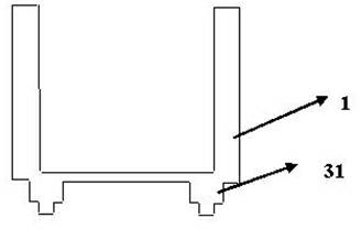
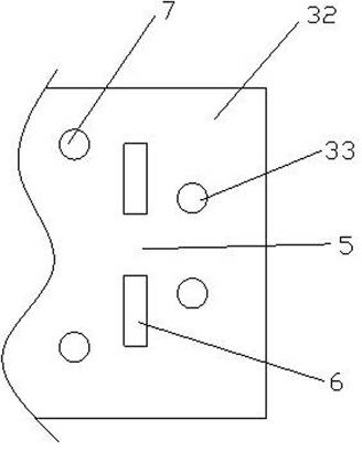
[0028] figure 1 and figure 2 Shown, the implementation of the present invention mainly comprises box body 1 and column 3, the both sides of box body 1 (the plan view of box body 1 is rectangular structure substantially, and two long sides of rectangular structure are the both sides of box body 1, two sides The short sides are the two ends of the box body 1 ) with protruding positioning buckles 4 (also called positioning pins) and positioning slots 8 .

[0029] Wherein, the positioning pin 4 is a protruding wall with a T-shaped cross section protruding outward along one side of the box body 1. In order to strengthen the strength of the positioning pin 4, metal reinforcing ribs can be embedded in the positioning pin 4. The reinforcing rib and The shape of the positioning pins is consistent, and the outside of the reinforcing rib is covered wit...


PUM


Abstract

The present invention relates to a casing of a battery pack, which includes a box body in which a battery pack is arranged. The outer wall of one side of the box has a protruding positioning buckle, and the outer wall of the other side has a protruding The positioning groove, the positioning buckle, its size is smaller than the positioning groove, so as to be embedded or inserted in the positioning groove of the adjacent shell during assembly, and the combination of the box is carried out. The present invention improves the shell structure of the battery pack , Various combinations can be made by using the shell of the battery pack. On the basis of the existing battery pack shell, a variety of combination designs can be carried out according to the actual application situation, so as to meet the matching requirements of the battery pack in various places. It is convenient for the series and parallel connection of batteries, which is convenient for wider application of batteries.

Description

technical field [0001] The invention relates to a battery, specifically a casing for a battery pack. The casing is suitable for different types of batteries and can facilitate the connection between different casings. Background technique [0002] Battery packs, as the power of electric vehicles or electric equipment, usually require multiple batteries to be installed in one casing in various ways, such as a single lead battery assembly for electric bicycles described in patent application 201020273175.7 A box, which includes: a box body and its external terminals, and a number of single batteries. The inside of the box body is equipped with a number of vertically and horizontally distributed ribs to form a grid-like plug-in unit; the plug-in unit accommodates 1 or more single batteries; the box is also equipped with a combination of several hard materials with holes or / and several fasteners for grouping several single batteries The mechanical connection is several fasteni...

Claims


Application Information

Patent Timeline
Patent Type & Authority Applications(China)
IPC IPC(8): H01M2/10
CPCY02E60/12Y02E60/10
Inventor 吕江英周德清
Owner 深圳市益佳通科技股份有限公司
Learn More