Tensile Integral Deployable Antenna

A technology of tensegrity and antenna, which is applied in the direction of folding antennas, etc., can solve the problems of large folded volume, low unfolded reliability, and difficulty in increasing the antenna diameter, etc., to achieve reduced folded volume, high unfolded reliability, and reduced emission cost effect

Inactive Publication Date: 2011-12-14
XIDIAN UNIV
View PDF4 Cites 29 Cited by
  • Summary
  • Abstract
  • Description
  • Claims
  • Application Information

AI Technical Summary

Problems solved by technology

Since the height of the surrounding truss unfolded structure in the folded state is the sum of the two sides of the parallelogram, the folded volume is relatively large; at the same time, since the unfolding of the ring truss is driven by a rope, the unfolding reliability is low, and in order to drive th

Method used


Image

  • Tensile Integral Deployable Antenna
  • Tensile Integral Deployable Antenna
  • Tensile Integral Deployable Antenna

Examples


Embodiment Construction

[0021] Below in conjunction with accompanying drawing, the invention is further described.

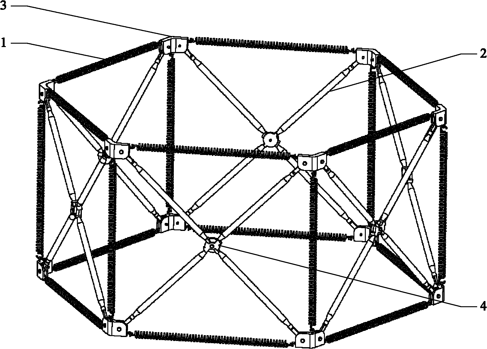
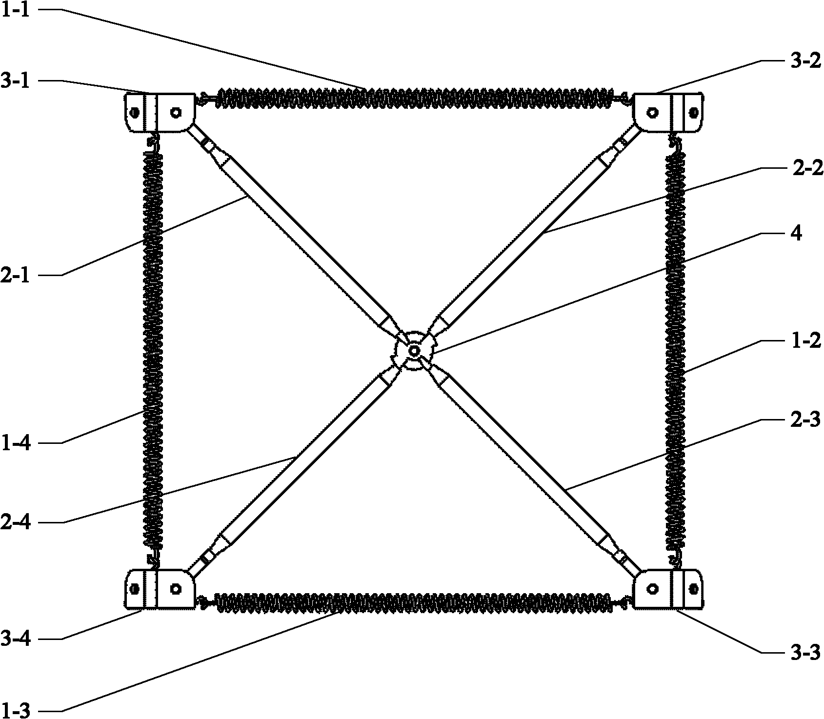
[0022] refer to figure 1 , the present invention includes n quadrilateral plane expansion units, n≥6, 6 is taken in this example, each plane expansion unit includes four springs 1, four support rods 2, four Hooke hinge joints 3 and plane rotation pairs 4, These planar unfolded units are connected by Hooke hinge joints 3 to form a regular polygonal prism-shaped unfolded structure. in:

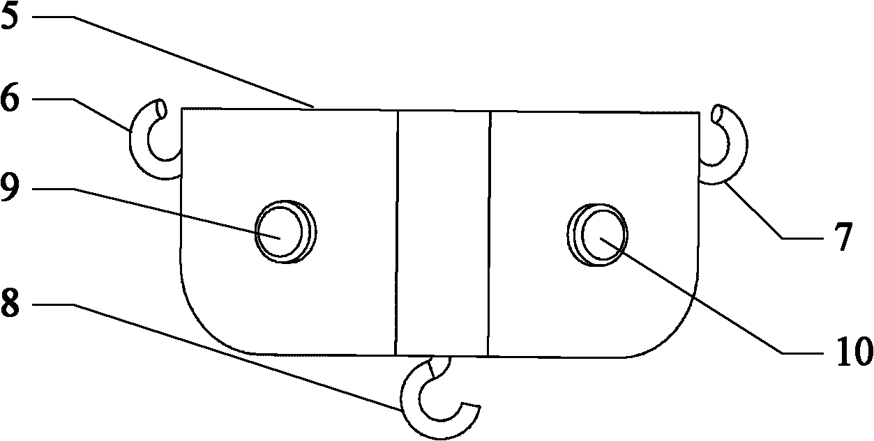
[0023] The structure of the Hooke hinge joint is as follows image 3 As shown, it includes a connecting frame 5, a pair of pins 9 and 10, a pair of horizontal hooks 6 and 7, and a vertical hook 8.

[0024] The structure of the planar revolving pair 4 is as follows Figure 4 Shown, it comprises upper chuck 4-1 and lower chuck 4-2, is connected by pin 4-3 between upper chuck 4-1 and lower chuck 4-2, upper chuck 4-1 and lower chuck All have limit block 4-4 on the disk 4-2.

[0025] The two ends of the...


PUM


Abstract

The invention discloses a tension integral deployable antenna, which mainly solves the problems of large folded volume and low deployment reliability in the prior art. It consists of n quadrilateral planar expansion units connected to each other through Hooke hinge joints (3) to form a regular polygonal prism-shaped expansion structure; each quadrilateral planar expansion unit adopts a spring frame structure, and the center adopts four support rods (2) and rotating The pair (4) is fixedly connected to form a cross-shaped retractable structure, and the two straight rods of the cross-expanded structure can rotate relatively around the central axis of the plane rotating pair; through the second spring (1-2) of each quadrilateral plane unfolding unit And the tension of the fourth spring (1-4) makes the overall structure unfold from the folded state. The invention has the characteristics of high deployment reliability and small folded volume, and is particularly suitable as a deployment structure for large spaceborne antennas, and can be used in the field of aerospace.

Description

technical field [0001] The invention belongs to the technical field of antennas, in particular to a tensioned integral expandable antenna, which realizes the automatic expansion of the antenna and can be used as a space reflector antenna. Background technique [0002] Spacecraft, especially satellite antennas, have become an indispensable part of any space system. Spacecraft antennas affect and restrict the performance and functions of the entire wireless communication system and even the entire spacecraft. Antenna technology has become an important part of promoting the technological progress and important factor in the development of space applications. [0003] In order to meet the needs of functions such as multi-function, multi-band, large capacity, high power, and long life, satellite antennas inevitably tend to be larger in diameter. Because space equipment equipped with antennas needs to be sent into space by rockets, satellite antennas must be made foldable, that i...

Claims


Application Information

Patent Timeline
IPC IPC(8): H01Q1/08
Inventor 李团结曹玉岩林占超薛碧洁尚菲
Owner XIDIAN UNIV
Why Eureka
Try Eureka