
Apparatus and method for estimating signal direction angle and its communication system

A communication system and signal technology, applied in multi-frequency code system, diversity/multi-antenna system, space transmit diversity, etc., can solve the problems of destroying system orthogonality, system performance error continuation, etc.

Active Publication Date: 2011-12-14
IND TECH RES INST
View PDF6 Cites 7 Cited by
  • Summary
  • Abstract
  • Description
  • Claims
  • Application Information

AI Technical Summary

Problems solved by technology

[0007] However, when broadband wireless communication is performed under high-speed movement, the communication signal will be affected by the Doppler Effect (Doppler Effect)
The Doppler effect is mainly due to the carrier frequency offset caused by the relative speed, and this offset will cause the Inter Carrier Interference (ICI) effect under the OFDM technology used in broadband wireless communication, which will destroy the system. Orthogonality makes the system performance produce the error continuation (Error Floor) phenomenon

Method used


Image

  • Apparatus and method for estimating signal direction angle and its communication system
  • Apparatus and method for estimating signal direction angle and its communication system
  • Apparatus and method for estimating signal direction angle and its communication system

Examples


Embodiment Construction

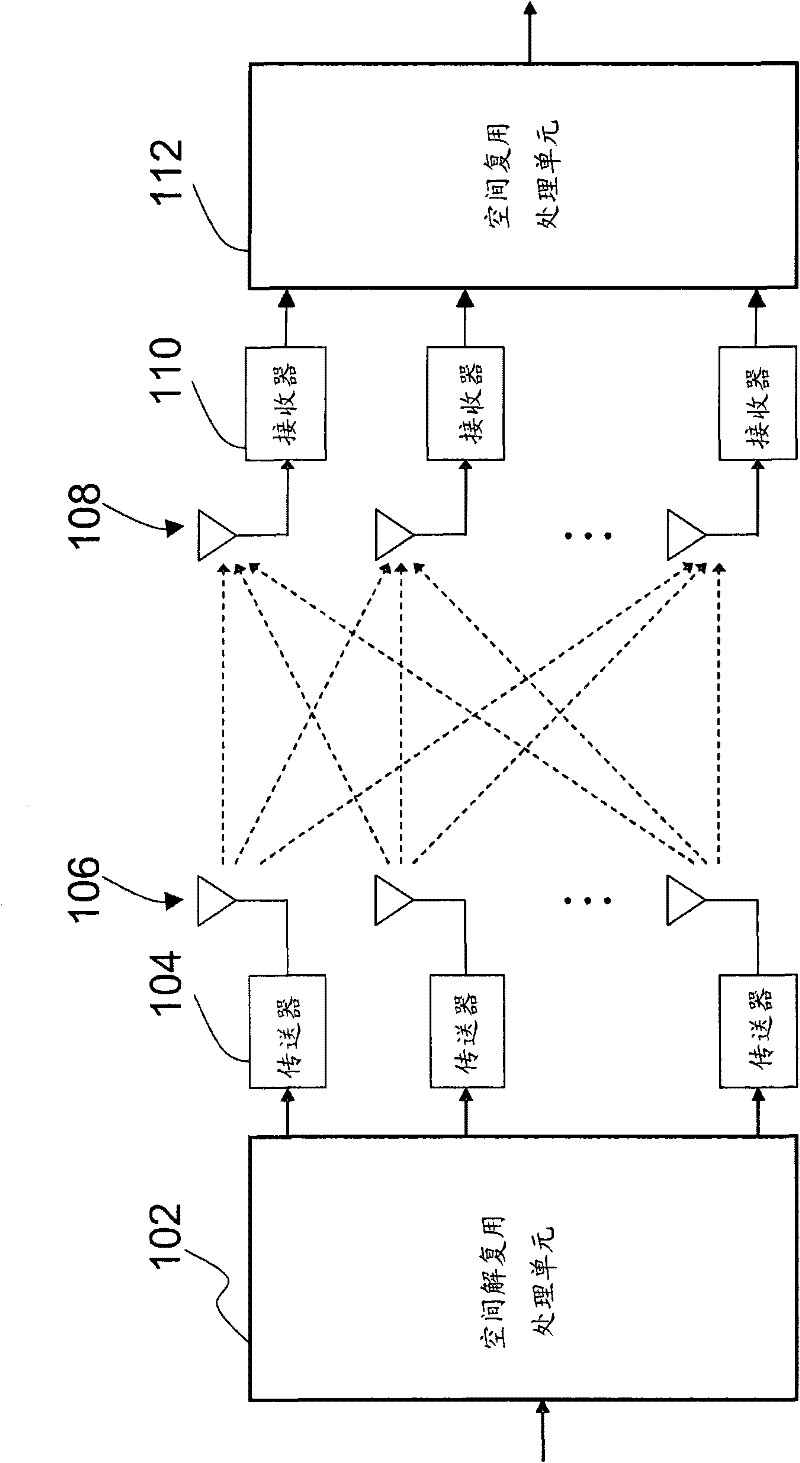
[0045] Please refer to figure 1 , which shows an embodiment of a MIMO system structure diagram using spatial multiplexing (Spatial Multiplexing). After the signal is processed by a spatial demultiplexing unit 102 , it is processed by N transmitters 104 and transmitted by an antenna array 106 having N antennas. After the transmitted signal is received by the antenna array 108 having M antennas, it is processed by the M receivers 110 and the spatial multiplexing processing unit 112 to generate corresponding signals.

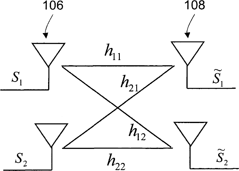
[0046] The description is now simplified by assuming that both N and M have a value of 2. Please refer to figure 2, which shows the relationship between the antenna array 106 with 2 antennas and the antenna array 108 with 2 antennas during spatial multiplexing processing. The signal S transmitted by the antenna array 106 1 with S 2 and the signal received by the antenna array 108 and has the following relationship:

[0047] ...


PUM


Abstract

The invention relates to an estimation device and device for a signal incoming angle and a communication system thereof. The estimation device for the signal incoming angle comprises a generating unit, a relativity calculating unit and a selecting unit, wherein the generating unit is used for generating a Doppler shift table, and the Doppler shift table comprises a plurality of candidate Doppler shift matrixes which correspond to a plurality of candidate incident angles under a relative motion speed; the relativity calculating unit is used for calculating the relativities of a received signal with the plurality of candidate Doppler shift matrixes; and the selecting unit is used for selecting the candidate incident angle corresponding to the highest relativity of the received signal with the plurality of candidate Doppler shift matrixes so as to determine the signal incoming angle.

Description

technical field [0001] The present invention relates to an estimating device and method and its communication system, and in particular to an estimating device and method for a signal direction angle and its communication system. Background technique [0002] The Multi Input Multi Output (MIMO) technology has attracted more and more attention in recent years due to its advantages of improving system performance and increasing data transmission throughput (Throughput). The beam-forming (Beam-Forming) technology derived from the MIMO technology is becoming more and more common in use. The beamforming technology mainly uses the information of the direction of arrival (DOA) of the signal to adaptively adjust the orientation of the antenna array pattern (Pattern) when receiving the signal, to increase the strength of the received signal, or to suppress Inter-antenna interference due to multi-path fading channel effects. [0003] The beamforming technology is mainly divided into...

Claims


Application Information

Patent Timeline
Patent Type & Authority Applications(China)
IPC IPC(8): H04B7/08H04L27/26
Inventor 曾铭健林信标郑名宏林坤毅
Owner IND TECH RES INST
Learn More