
Constant force intraocular lens injector

A technology of intraocular lens and resistance, applied in the direction of syringes, intraocular lenses, and medical equipment, can solve troubles and other problems

Inactive Publication Date: 2011-12-14
ALCON RES LTD
View PDF4 Cites 1 Cited by
  • Summary
  • Abstract
  • Description
  • Claims
  • Application Information

AI Technical Summary

Problems solved by technology

However, screw-type manual injectors require the use of two hands, which is cumbersome and tedious

Method used


Image

  • Constant force intraocular lens injector
  • Constant force intraocular lens injector
  • Constant force intraocular lens injector

Examples


Embodiment Construction

[0018] Reference will now be made in detail to the exemplary embodiments of the present invention, examples of which are illustrated in the accompanying drawings.

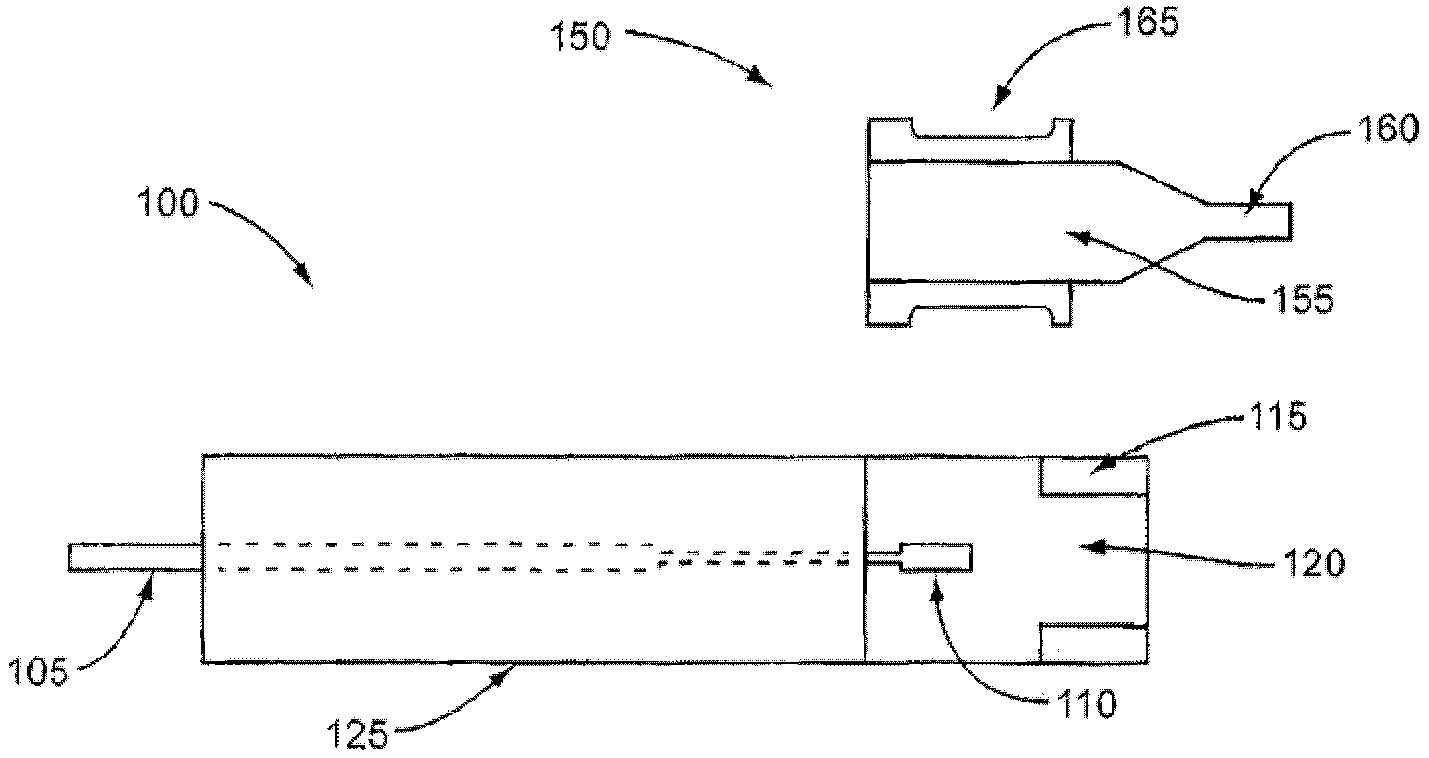
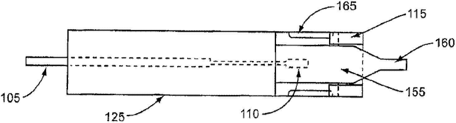
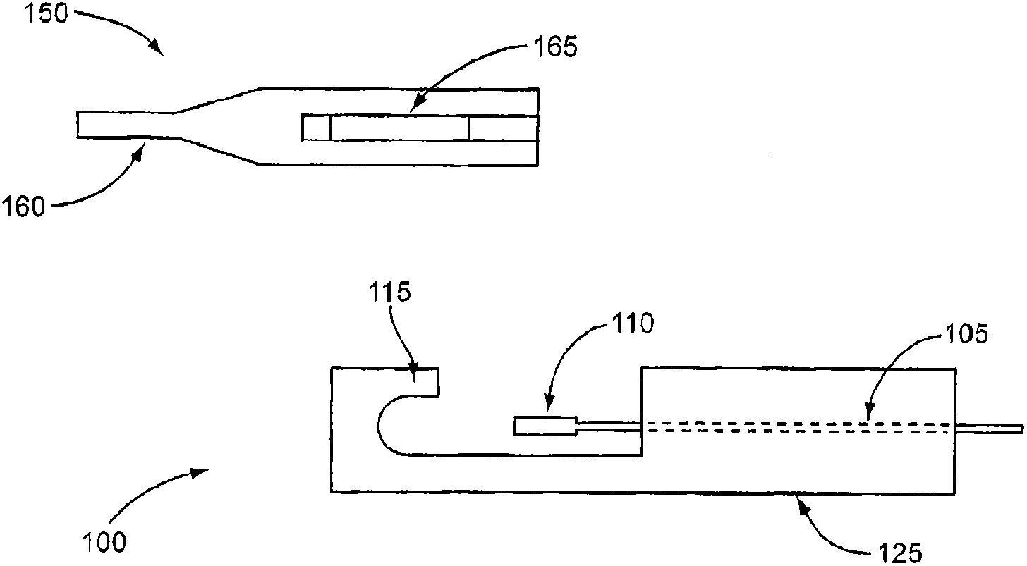
[0019] figure 1 is a top cross-sectional view of the cartridge and handpiece used together as an intraocular lens (IOL) injector. exist figure 1 In the illustrated embodiment, the two-piece IOL injector system includes a handpiece 100 and a barrel 150 . The handpiece 100 includes a tubular injector housing 125 housing the plunger rod 105 connected to the plunger 110 . The plunger rod 105 is generally rigid and is connected to the plunger 110 such that movement of the rod 105 is translated into movement of the plunger 110 . In this manner, the plunger 110 is designed to translate longitudinally within the injector housing along the injector housing 125 . Those skilled in the art will appreciate that in some embodiments the plunger rod 105 and plunger 110 may comprise, for example, a molded plastic unitary piece,...


PUM


Abstract

An intraocular lens injection device comprising a tubular housing (125, 610, 710, 810) having a channel extending along its longitudinal axis and a plunger rod (105, 620) disposed within and movable along the channel. , 720, 820). The tubular housing and the plunger rod have a frictional engagement member configured to produce varying intrusive friction as the plunger moves through its working range, thereby compensating One or more changes in the breakout resistance. Varying the intrusion friction may comprise one or more step changes in the unloaded intrusion friction in at least a portion of the working range of the plunger rod, or a curvilinear change in the intrusion friction, or compensate for both. In some embodiments, a slot (640) of varying width in the housing frictionally engages a protrusion (630) extending laterally from the plunger rod. In other embodiments, a contoured surface on the plunger rod frictionally engages an aperture (730, 830) in the tubular housing.

Description

technical field [0001] The present invention relates generally to devices for delivering intraocular lenses into the eye, and more particularly to techniques for compensating for changes in resistance to implantation of the lens. Background technique [0002] The human eye is used to provide vision by transmitting light through a transparent outer part called the cornea and focusing the image onto the retina by means of a lens. The quality of the focused image depends on many factors, including the size and shape of the eye, and the transparency of the cornea and lens. When age or disease causes the lens to become less transparent, vision decreases because less light can be transmitted to the retina. This defect in the lens of the eye is medically known as a cataract and can be treated by surgically removing the lens and replacing the lens function with an artificial intraocular lens (IOL). [0003] In the United States, most cataractous lenses are removed through a surgic...

Claims


Application Information

Patent Timeline
IPC IPC(8): A61F2/16
CPCA61F2250/0021A61F2/167A61F2/1678A61F9/007A61M31/00A61M5/178A61F2/14
Inventor A·阿尔齐科沃韦奇M·伯克尼
Owner ALCON RES LTD
Features
  • Generate Ideas
  • Intellectual Property
  • Life Sciences
  • Materials
  • Tech Scout
  • Unparalleled Data Quality
  • Higher Quality Content
  • 60% Fewer Hallucinations
Learn More