Controller for internal combustion engine

A control device, a technology for an internal combustion engine, applied in engine control, fuel injection control, electrical control, etc., and can solve problems such as excess oxygen adsorption

Inactive Publication Date: 2014-02-26
TOYOTA JIDOSHA KK
View PDF9 Cites 0 Cited by
  • Summary
  • Abstract
  • Description
  • Claims
  • Application Information

AI Technical Summary

Problems solved by technology

[0008] In addition, when the fuel cut is performed, the EGR catalyst also excessively absorbs oxygen

Method used


Image

  • Controller for internal combustion engine
  • Controller for internal combustion engine
  • Controller for internal combustion engine

Examples


Embodiment approach 1

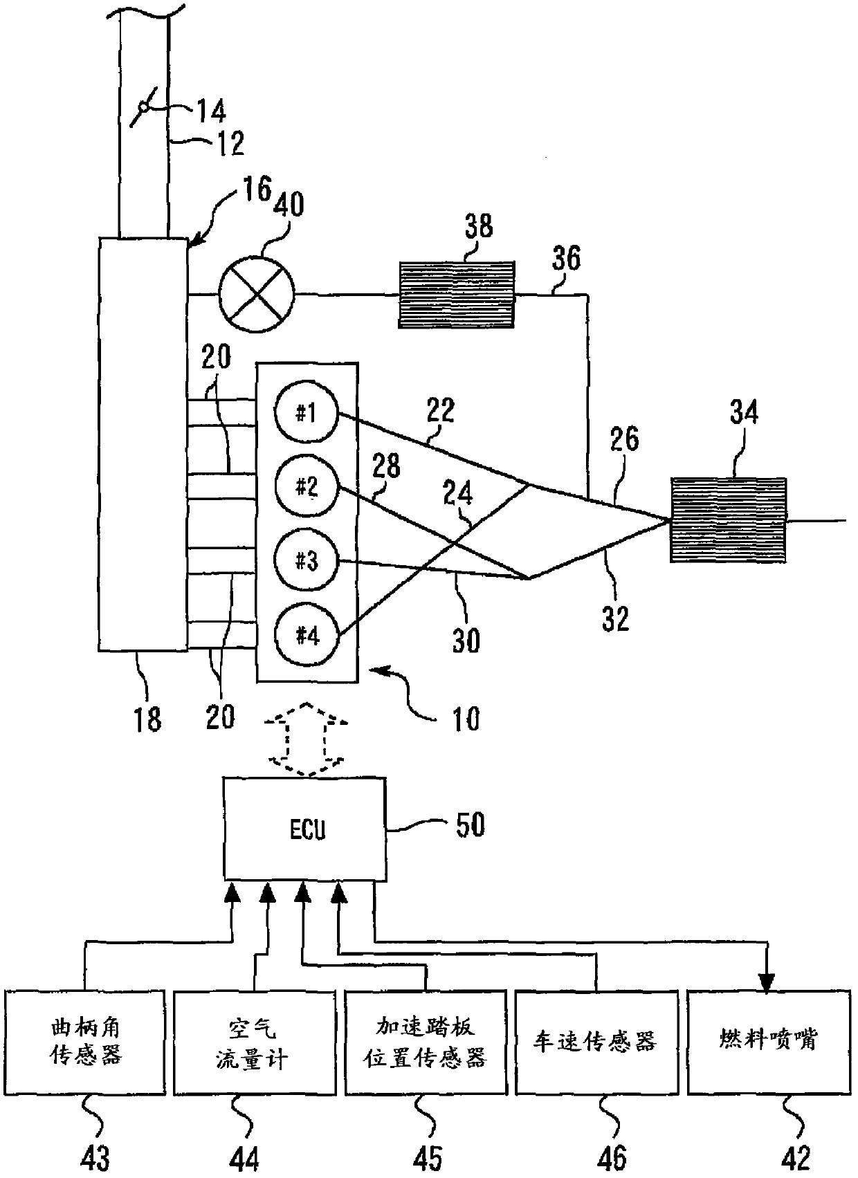
[0025] Embodiment 1 A diagram illustrating a system configuration according to Embodiment 1 of the present invention. Such as figure 1 As shown, the system of this embodiment includes an internal combustion engine (hereinafter simply referred to as an engine) 10 mounted on a vehicle or the like. The engine 10 of the present embodiment is an inline four-cylinder engine including four cylinders #1 to #4. The burning sequence is #1→#3→#4→#2. Although not shown, each cylinder is provided with a piston, an intake valve, an exhaust valve, a spark plug, and a fuel nozzle 42 .

[0026] A throttle valve 14 is provided in an intake passage 12 that supplies intake air to the engine 10 . The intake passage 12 is connected to the engine 10 via an intake manifold 16 . The suction header 16 has a surge tank 18 and four suction branch pipes 20 protruding from the surge tank 18 . Each air intake branch pipe 20 is connected to the air intake port of each cylinder respectively.

[0027] An...

Embodiment approach 2

[0063] Next, refer to image 3 Embodiment 2 of the present invention will be described, but only the points of difference from Embodiment 1 described above will be described, and descriptions of the same items will be simplified or omitted.

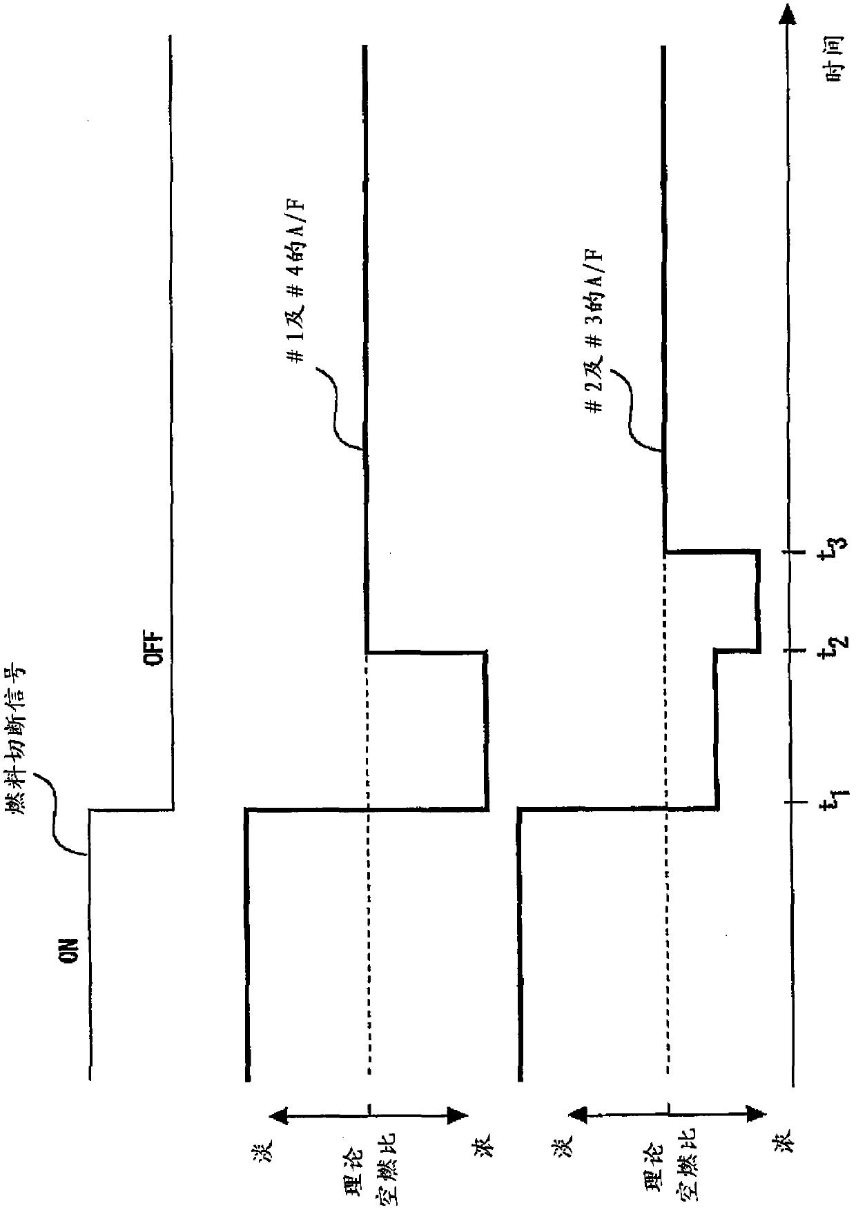
[0064] In the enrichment control in Embodiment 1 described above, the control is such that the adjustment of the oxygen storage amounts of both the exhaust purification catalyst 34 and the EGR catalyst 38 is completed simultaneously. On the other hand, in the present embodiment, the adjustment of the oxygen storage amount of the EGR catalyst 38 is controlled to be completed before the adjustment of the oxygen storage amount of the exhaust purification catalyst 34 is completed.

[0065] image 3 It is a time chart showing changes in the air-fuel ratios of the #1 cylinder and #4 cylinder and changes in the air-fuel ratios of the #2 cylinder and #3 cylinder after recovery from the fuel cut in the present embodiment. exist image 3 In the ...

Embodiment approach 3

[0075] Next, refer to Figure 4 Embodiment 3 of the present invention will be described, but only the points of difference from the above-mentioned Embodiments 1 and 2 will be described, and descriptions of the same matters will be simplified or omitted.

[0076]In Embodiments 1 and 2 described above, the description has been made in which EGR is executed immediately after returning from the fuel cut. However, EGR may not be executed immediately after returning from the fuel cut, but may be started in the middle of execution of the enrichment control. For example, although the engine is in the EGR prohibition operation region shortly after recovery from the fuel cut, the required engine load increases, and the vehicle may shift to the EGR allowment operation region.

[0077] In the present embodiment, when EGR is started in the middle of the enrichment control, the adjustment of the oxygen storage amount of the EGR catalyst 38 is controlled to be completed before the adjustme...


PUM


Abstract

An object of the present invention is that after return from fuel cut, an oxygen storage amount in a catalyst in an exhaust path and an oxygen storage amount in a catalyst in an exhaust gas recirculating path are promptly adjusted to be in appropriate states, respectively. A control apparatus for an internal combustion engine of the present invention controls the internal combustion engine including a recirculating gas generating cylinder and a recirculating gas nongenerating cylinder. The control apparatus includes: an exhaust gas recirculating path for connecting the exhaust path through which exhaust gas only in the recirculating gas generating cylinder is delivered and an intake system; a recirculating catalyst provided on the exhaust gas recirculating path; and rich control means that performs rich control for controlling an air-fuel ratio to be temporarily richer than a theoretical air-fuel ratio when fuel injection is restarted after return from the fuel cut. The rich control means includes air-fuel ratio control means that controls an air-fuel ratio in the recirculating gas generating cylinder to be richer than an air-fuel ratio in the recirculating gas nongenerating cylinder when the rich control and an exhaust gas recirculation by the exhaust gas recirculating path are simultaneously performed.

Description

technical field [0001] The invention relates to a control device for an internal combustion engine. Background technique [0002] An internal combustion engine that has an EGR passage that connects an exhaust passage and an intake passage of the internal combustion engine, and that can perform exhaust gas recirculation (EGR) through which a part of the exhaust gas flows back into the intake passage is widely used. (For example, refer to Patent Document 1). [0003] Patent Document 1: Japanese Patent Laid-Open No. 2003-3879 [0004] Patent Document 2: Japanese Patent Laid-Open No. 2007-9779 [0005] When performing EGR, deposits are likely to accumulate in the EGR passage, EGR cooler, suction port, suction valve, etc. One of the reasons for the accumulation of deposits is that unburned HC, NO X , PM, etc. Therefore, in order to suppress the accumulation of the above-mentioned deposits, it has been proposed to install a catalyst (EGR catalyst) for purifying exhaust gas on...

Claims


Application Information

Patent Timeline
Patent Type & Authority Patents(China)
IPC IPC(8): F02D41/14F02D41/18
CPCF02D41/0295F02M25/07F02D41/126F02D41/0065F01N2430/06F02D41/0082F01N2900/1624F01N13/107F02M26/35F02M26/43
Inventor 宫下茂树
Owner TOYOTA JIDOSHA KK
Why Eureka
Try Eureka