Control devices for internal combustion engines
A technology for control devices and internal combustion engines, applied in engine control, fuel injection control, electrical control, etc., can solve problems such as excess oxygen adsorption
- Summary
- Abstract
- Description
- Claims
- Application Information
AI Technical Summary
Problems solved by technology
Method used
Image
Examples
Embodiment approach 1
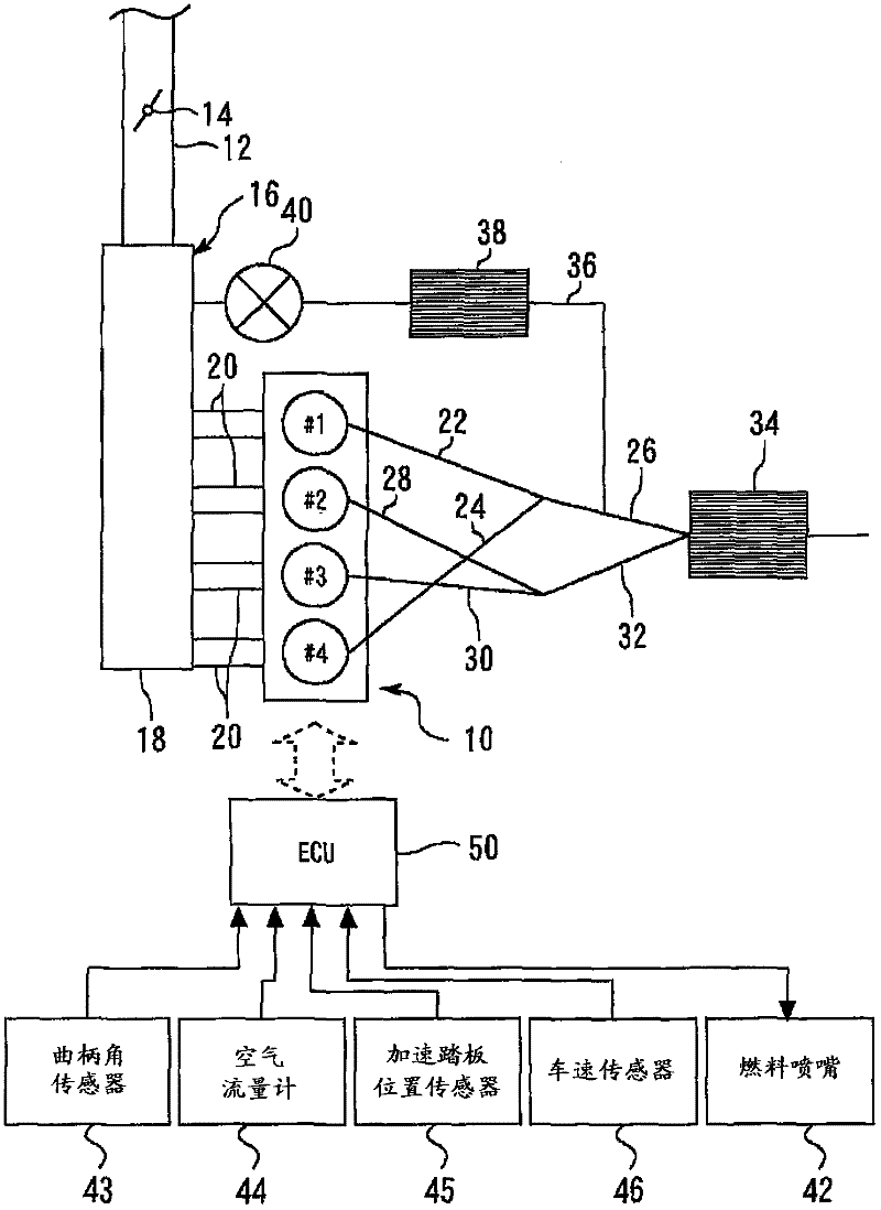
[0025] Embodiment 1 A diagram illustrating a system configuration according to Embodiment 1 of the present invention. Such as figure 1 As shown, the system of this embodiment includes an internal combustion engine (hereinafter simply referred to as an engine) 10 mounted on a vehicle or the like. The engine 10 of the present embodiment is an inline four-cylinder engine including four cylinders #1 to #4. The burning sequence is #1→#3→#4→#2. Although not shown, each cylinder is provided with a piston, an intake valve, an exhaust valve, a spark plug, and a fuel nozzle 42 .
[0026] A throttle valve 14 is provided in an intake passage 12 that supplies intake air to the engine 10 . The intake passage 12 is connected to the engine 10 via an intake manifold 16 . The suction header 16 has a surge tank 18 and four suction branch pipes 20 protruding from the surge tank 18 . Each air intake branch pipe 20 is connected to the air intake port of each cylinder respectively.
[0027] An...
Embodiment approach 2
[0063] Next, refer to image 3 Embodiment 2 of the present invention will be described, but only the points of difference from Embodiment 1 described above will be described, and descriptions of the same items will be simplified or omitted.
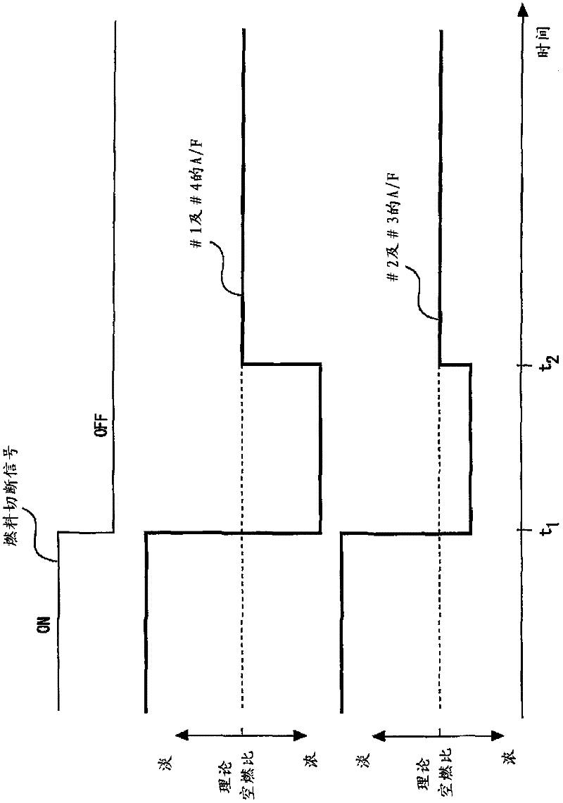
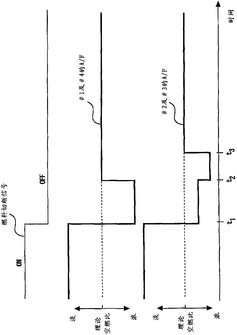
[0064] In the enrichment control in Embodiment 1 described above, the control is such that the adjustment of the oxygen storage amounts of both the exhaust purification catalyst 34 and the EGR catalyst 38 is completed simultaneously. On the other hand, in the present embodiment, the adjustment of the oxygen storage amount of the EGR catalyst 38 is controlled to be completed before the adjustment of the oxygen storage amount of the exhaust purification catalyst 34 is completed.
[0065] image 3 It is a time chart showing changes in the air-fuel ratios of the #1 cylinder and #4 cylinder and changes in the air-fuel ratios of the #2 cylinder and #3 cylinder after recovery from the fuel cut in the present embodiment. exist image 3 In the ...
Embodiment approach 3
[0075] Next, refer to Figure 4 Embodiment 3 of the present invention will be described, but only differences from the above-mentioned Embodiments 1 and 2 will be described, and descriptions of the same matters will be simplified or omitted.
[0076]In Embodiments 1 and 2 described above, the description has been made in which EGR is executed immediately after returning from the fuel cut. However, EGR may not be executed immediately after returning from the fuel cut, but may be started in the middle of execution of the enrichment control. For example, although the engine is in the EGR prohibition operation region shortly after recovery from the fuel cut, the required engine load increases, and the vehicle may shift to the EGR allowment operation region.
[0077] In the present embodiment, when EGR is started in the middle of the enrichment control, the adjustment of the oxygen storage amount of the EGR catalyst 38 is controlled to be completed before the adjustment of the oxy...
PUM
 Abstract
Description
Claims
Application Information
 - R&D
- Intellectual Property
- Life Sciences
- Materials
- Tech Scout
- Unparalleled Data Quality
- Higher Quality Content
- 60% Fewer Hallucinations
Browse by: Latest US Patents, China's latest patents, Technical Efficacy Thesaurus, Application Domain, Technology Topic, Popular Technical Reports.
© 2025 PatSnap. All rights reserved.Legal|Privacy policy|Modern Slavery Act Transparency Statement|Sitemap|About US| Contact US: help@patsnap.com


