Electronic equipment
An electronic device and a technology for setting time, which can be used in the separation of dispersed particles, projection devices, and filtration of dispersed particles, which can solve problems such as undeveloped equipment.
- Summary
- Abstract
- Description
- Claims
- Application Information
AI Technical Summary
Problems solved by technology
Method used
Image

Examples
Embodiment approach 1
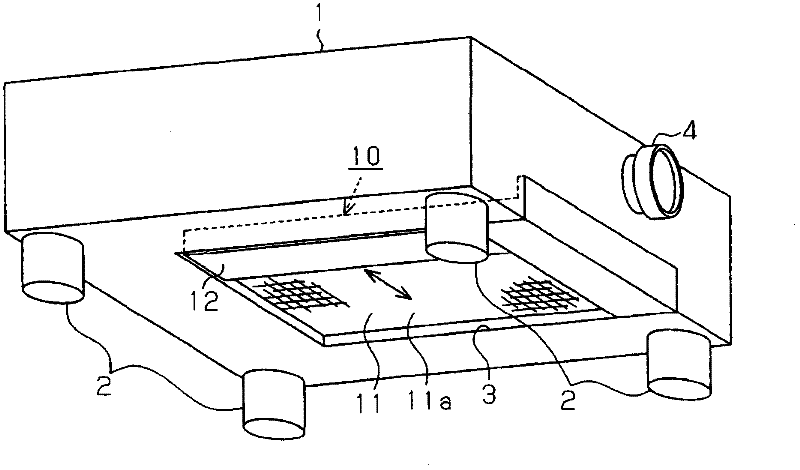
[0038] Hereinafter, a projection-type image display device as an electronic device according to Embodiment 1 of the present invention will be described with reference to the drawings. In addition, in the following description, when referring to the up, down, left, and right directions or the front and rear directions, the up, down, left, and right directions or the front and rear directions in each drawing are referred to.
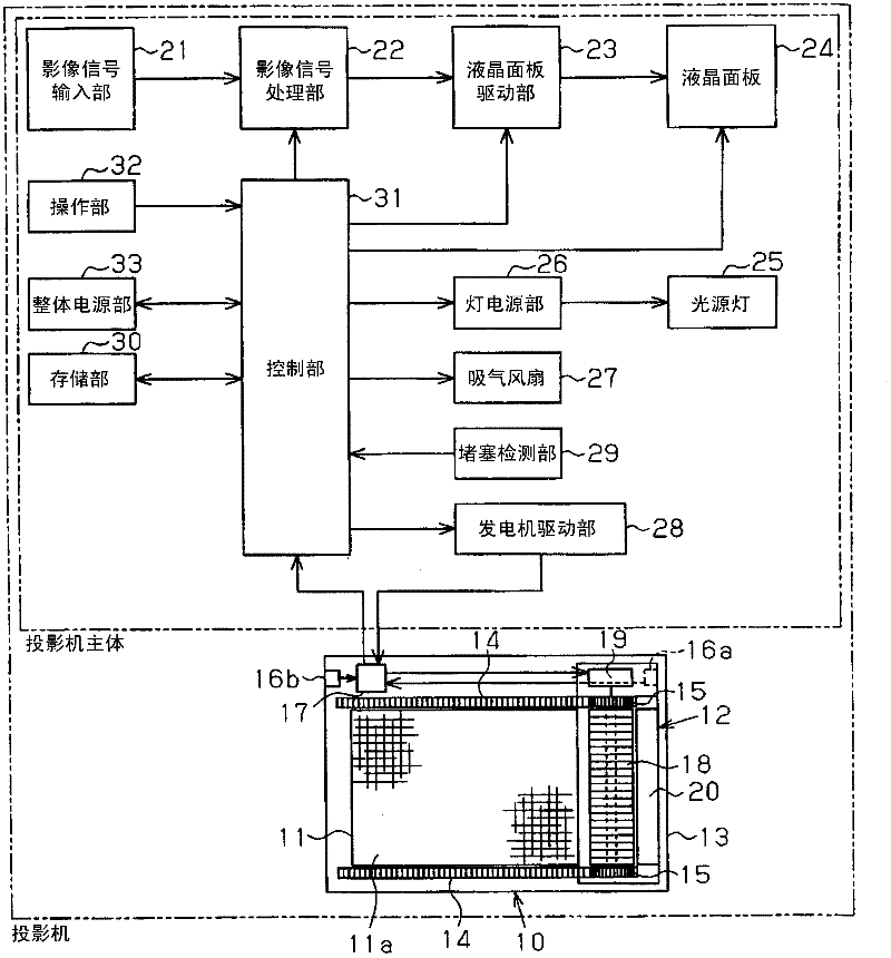
[0039] The projection-type video display device as the electronic equipment in this embodiment is a three-panel projection-type video display device, which has such figure 1 The box-shaped packing box 1 shown in the perspective view of the appearance. The packaging box 1 has leg portions 2 at four corners of the bottom, and is configured to suck air outside the equipment as cooling air from the bottom. In addition, in the packaging box 1, an air filter device is arranged at the air intake port 3 for introducing air outside the device into the device.
[...
Embodiment approach 2
[0068] Next, with respect to the projection type video display device of the second embodiment, refer to Figure 4 The flow chart is explained. The projection-type video display device of the second embodiment is different from the projection-type video display device of the first embodiment in the cleaning operation process. The following description will focus on the cleaning operation step, which is different from the first embodiment.
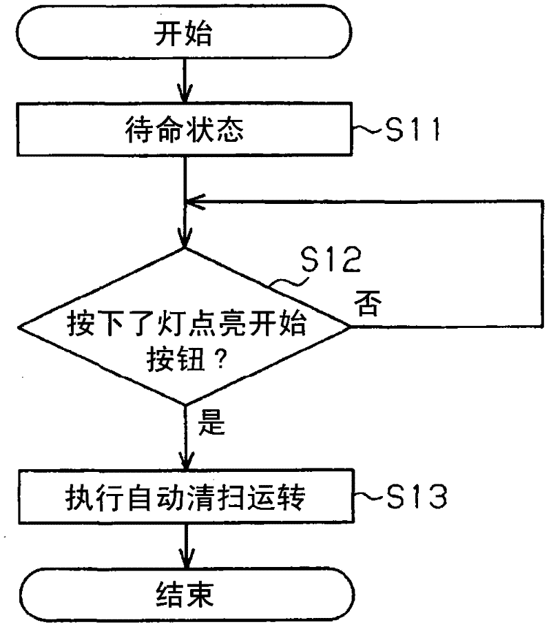
[0069] The cleaning operation process of the second embodiment is as follows: Figure 4 As shown, steps S21 to S23 in this embodiment are the same as steps S11 to S13 in the first embodiment. The lamp lighting start button in the present embodiment is the operation switch of the operation unit 32 as in the case of the first embodiment. Then, when the lamp lighting start button is pressed to start the operation, first, the automatic cleaning operation of the air filter 11 is executed.
[0070] Next, the steady operation is performed afte...
Embodiment approach 3
[0075] Next, with respect to the projection-type video display device of the third embodiment, refer to Figure 5 and Image 6 The flow chart is explained. The projection-type video display device of the third embodiment differs from the projection-type video display device of the first embodiment in the cleaning operation process. The following description will focus on the cleaning operation step, which is different from the first embodiment.
[0076] The cleaning operation step of the third embodiment is as follows: Figure 5 As shown, as in the case of Embodiment 1, when the entire power supply unit 33 is connected to a power source such as a commercial power supply, it enters a so-called standby state in which the operation switch waits to be turned on (step S31 ), and it is determined whether or not the lamp lighting start is pressed. button (step S32). Furthermore, in the present embodiment, when the lighting start button is pressed (YES in step S32 ), the first aut...
PUM
 Abstract
Description
Claims
Application Information
 - R&D
- Intellectual Property
- Life Sciences
- Materials
- Tech Scout
- Unparalleled Data Quality
- Higher Quality Content
- 60% Fewer Hallucinations
Browse by: Latest US Patents, China's latest patents, Technical Efficacy Thesaurus, Application Domain, Technology Topic, Popular Technical Reports.
© 2025 PatSnap. All rights reserved.Legal|Privacy policy|Modern Slavery Act Transparency Statement|Sitemap|About US| Contact US: help@patsnap.com