Electric heating friction spot welding stirring head and its welding method

A stirring head and friction point technology, applied in the field of electric heating friction spot welding stirring head and its welding, can solve the problems of insufficient flow, difficult to form welds, limited friction heat, etc. The effect of improved shear tensile properties and increased width of the connection zone

Inactive Publication Date: 2011-12-21
CHONGQING UNIV
View PDF5 Cites 8 Cited by
  • Summary
  • Abstract
  • Description
  • Claims
  • Application Information

AI Technical Summary

Problems solved by technology

During the welding process, due to the limited frictional heat generated between the stirring head and the workpiece (the temperature generated by the frictional heat is generally l...

Method used


Image

  • Electric heating friction spot welding stirring head and its welding method
  • Electric heating friction spot welding stirring head and its welding method
  • Electric heating friction spot welding stirring head and its welding method

Examples


example 1

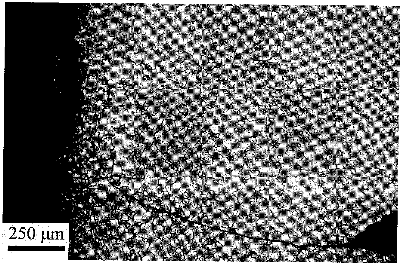
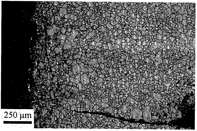
[0011] Before welding, the surface of the 2.5mm magnesium alloy AZ31 flat plate is ground and fixed on the clamping device, and the temperature of the high-temperature electric heating coil is adjusted to raise the temperature of the stirring head to 480°C, and then welding is performed after stabilization. During the friction stir spot welding process, the heating temperature of the high-temperature electric heating coil remains constant until the end of the welding process.

example 2

[0013] Before welding, the surface of the 2.5mm magnesium alloy AZ31 flat plate is ground and fixed on the clamping device, and the temperature of the high-temperature electric heating coil is adjusted to raise the temperature of the stirring head to 490°C, and welding is performed after stabilization. During the friction stir spot welding process, the heating temperature of the high-temperature electric heating coil remains constant until the end of the welding process.

example 3

[0015] Before welding, the surface of the 2.5mm magnesium alloy AZ31 plate is ground and fixed on the clamping device, and the temperature of the high-temperature electric heating coil is adjusted to raise the temperature of the stirring head to 500°C, and welding is performed after stabilization. During the friction stir spot welding process, the heating temperature of the high-temperature electric heating coil remains constant until the end of the welding process.


PUM


Abstract

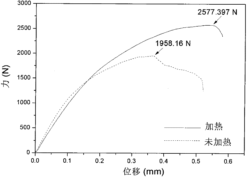
The invention relates to an electric heating friction spot welding stirring head and a welding method thereof, belonging to the friction stir welding technology. The electric heating friction spot welding stirring head is characterized in that the high-temperature electric heating ring is placed on the area between the shaft shoulder of the stirring head and the clamping part, and the high-temperature electric heating ring is fixed on the host mechanism for clamping the stirring head, which is beneficial to During the welding process, the high-temperature electric heating ring and the stirring head move synchronously. The welding method of the electric heating friction spot welding stirring head is to use a high-temperature electric heating coil to heat the stirring head before the friction stir spot welding, and perform welding when the temperature of the stirring head rises above the recrystallization temperature of the material to be welded and stabilizes. The heating temperature of the high-temperature electric heating coil remains constant until the end of the welding process. Compared with the friction stir spot welded joint without heating the stirring head, the welded joint obtained by this welding process has a nearly 25% increase in tensile properties, and solves the problem of difficult friction stir welding of materials with high melting point and low plasticity.

Description

technical field [0001] The invention relates to an electric heating friction spot welding stirring head and a corresponding welding method thereof, belonging to the friction stirring welding technology. Background technique [0002] In 1991, the British Welding Institute (TWI) invented a new type of solid-phase friction stir welding technology. During the application of this technology, it will not produce defects such as element evaporation, pores and cracks caused by traditional fusion welding. It is known as "The most revolutionary welding technology" has broad application prospects. Its working principle is that a high-speed rotating stirring head with a stirring needle is inserted into the workpiece, and the heat generated by the friction between the stirring head and the workpiece is used to partially soften the welded material, and the welded material undergoes plastic flow bonding under the stirring effect of the stirring head Welding together to form an inseparable...

Claims


Application Information

Patent Timeline
IPC IPC(8): B23K20/12
Inventor 沈骏王丹
Owner CHONGQING UNIV
Why Eureka
Try Eureka