Compound needle for flat knitting machine

A flat knitting machine and composite needle technology, applied in the field of composite needles, can solve problems such as increased driving load, increased sliding resistance, and insufficient rigidity, and achieve the effects of reducing sliding resistance, improving opening and closing precision, and reducing resistance

Active Publication Date: 2011-12-21
SHIMA SEIKI MFG LTD
View PDF12 Cites 2 Cited by
  • Summary
  • Abstract
  • Description
  • Claims
  • Application Information

AI Technical Summary

Problems solved by technology

However, when the slider moves relative to the needle body, the sliding resistance increases and the driving load increases.
In addition, since the blade is bent in the portion of the curved portion, there is a possibility that the portion away from the side wall surface in the blade pocket may not have sufficient rigidity.
Furthermore, there is a possibility that the bent shape of the tongue piece and the bent portion becomes complicated, and the finished shape becomes unstable.

Method used


Image

  • Compound needle for flat knitting machine
  • Compound needle for flat knitting machine
  • Compound needle for flat knitting machine

Examples


Embodiment Construction

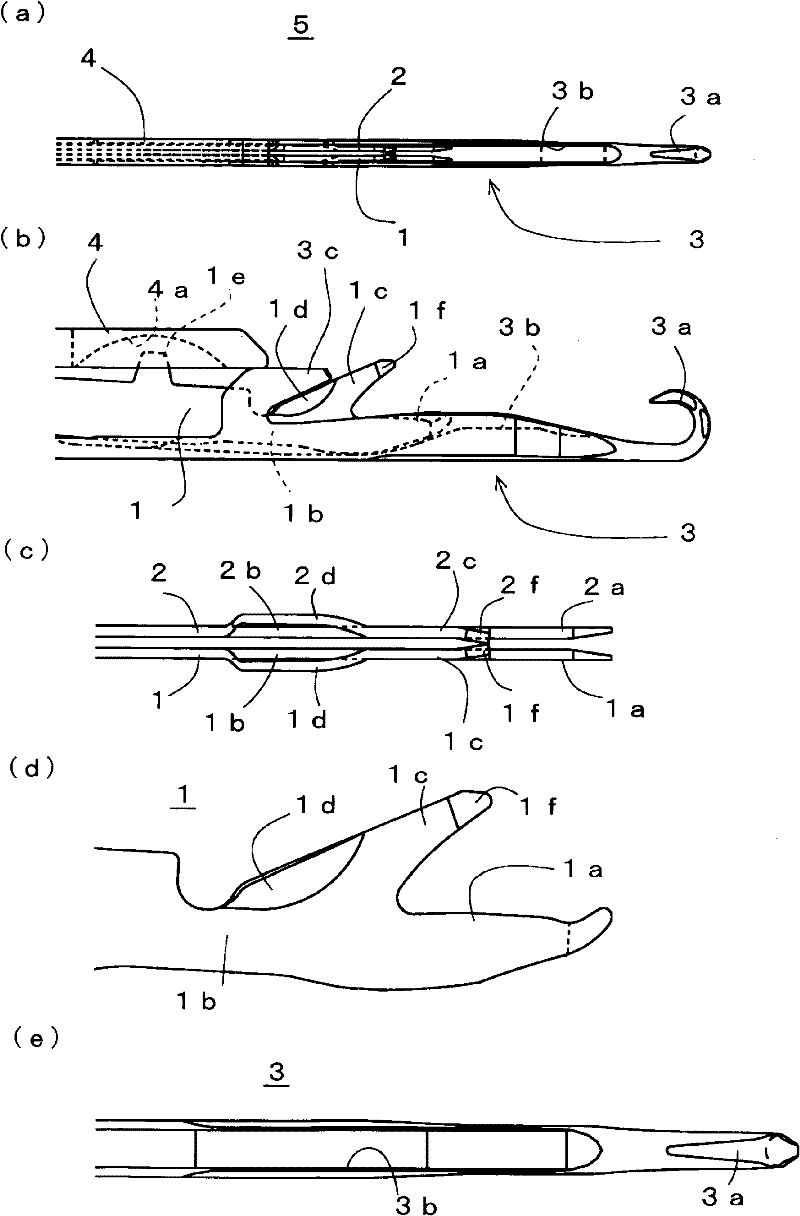
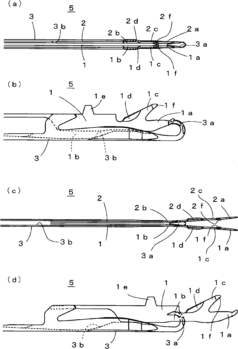
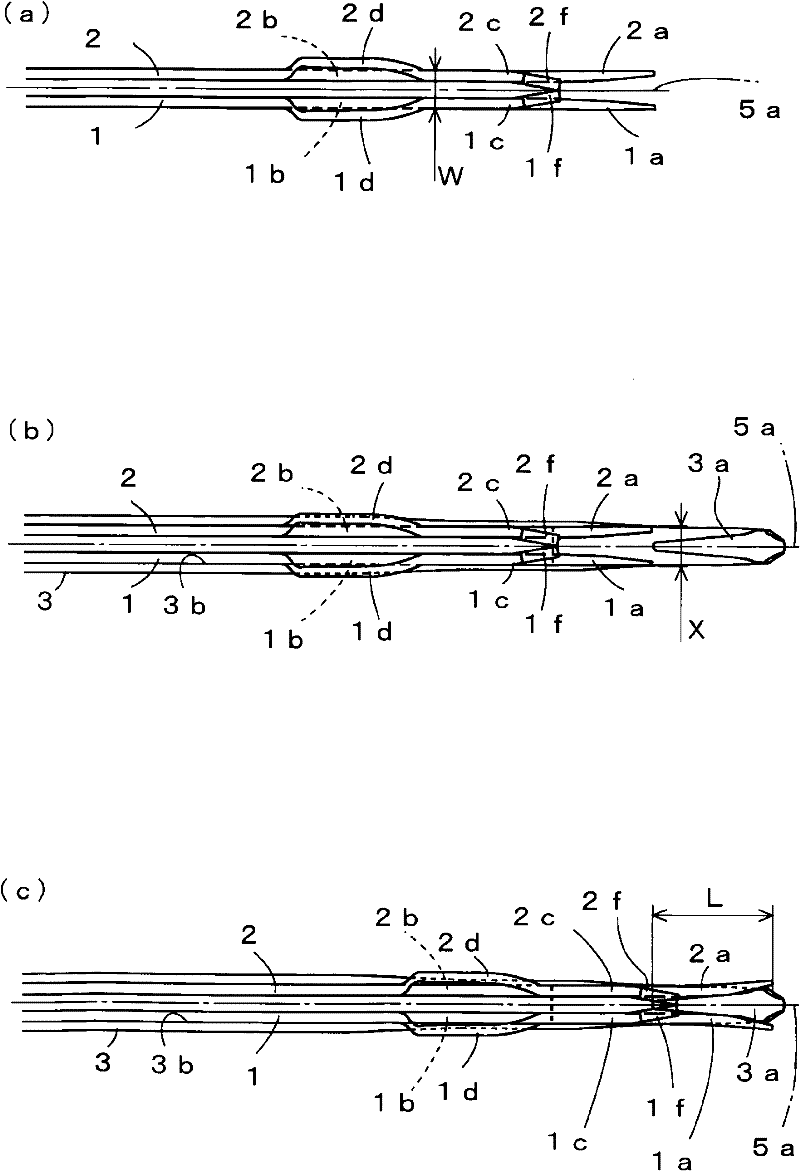
[0031] under, figure 1 The structures of the composite needle 5 and the two blades 1 and 2 are shown as one embodiment of the present invention. figure 2 express figure 1 The action state of compound needle 5. image 3 express figure 1 The action of the blade 1, 2. The blade 1 and the blade 2 are symmetrical about parallel planes provided at the center, and even if the blade 2 is omitted from illustration, a portion corresponding to the blade 1 exists in the blade 2 .

[0032] In addition, in the description of each figure, reference signs not attached to the figure to be described may be referred to by reference signs attached to the previously described figures. In addition, the compound needle 5 is shown in a state of being housed in a needle groove formed on a needle bed of a flat knitting machine, and illustration of the needle groove itself is omitted. However, although the needle bed of the flat knitting machine is inclined so as to become higher toward the front ...


PUM


Abstract

The present invention provides a compound needle for a flatbed knitting machine in which sliding resistance can be made small and opening / closing accuracy to an aperture of a hook by a tongue can be enhanced with a simple structure. Tongues (1a, 2a) have no bent and have linear shaped portions (1b, 2b) provided at the rear side of the tongues (1a, 2a), so that blades (1, 2) have stable finishing shapes and manufacturing thereof can be easily performed. Since lower portions of the blades (1, 2) are not bent in a blade groove, sliding resistance can be made small. Shoulder portions (1c, 2c) which come out of the blade groove from rear portions of the tongues (1a, 2a) are bent inward between the shoulder portions (1c, 2c) opposed to each other such that front ends of the shoulder portions (1c, 2c) make closer to and contact with each other so as to form contacting portions (1f, 2f), therefore, a centering effect can be obtained. A space generated between the tongues (1a, 2a) is kept so that resistance when a hook (3a) opens between the tongues (1a, 2a) can be made small and opening / closing accuracy of the hook 3a can be enhanced.

Description

technical field [0001] The invention relates to a compound needle of a flat knitting machine, which is accommodated in a needle groove formed on a needle bed of the flat knitting machine, and a slider for opening and closing a hook is formed by two blades. Background technique [0002] At present, in a flat knitting machine, the knitting needles housed in the needle grooves formed on the needle bed are driven to slide in the needle grooves, and the hooks at the front end are advanced and retreated in the tooth gaps, and the knitting needles supplied from the tooth gaps to the hooks are knit. Threads are woven into fabrics. As a knitting needle, a composite needle is sometimes used that combines a needle body having a hook at the tip and a slider that is movable relative to the needle body and has a tongue that opens and closes the hook at the tip. In the compound needle, a slider formed of two blades is also used so that both sides of the hook can be separated so as to pass...

Claims


Application Information

Patent Timeline
Patent Type & Authority Applications(China)
IPC IPC(8): D04B35/04D04B35/06
CPCD04B35/06D04B15/20D04B15/22D04B35/04
Inventor 北原健治
Owner SHIMA SEIKI MFG LTD
Why Eureka
Try Eureka