United energy device and construction method and application thereof
A construction method and energy technology, which are applied in the fields of transportation engineering, thermal power generation, civil engineering, energy engineering, and cable rail transportation engineering, can solve the problems of non-shared carrier, large investment and high cost, and improve the ability to draw cold air. Effect
- Summary
- Abstract
- Description
- Claims
- Application Information
AI Technical Summary
Problems solved by technology
Method used
Image
Examples
Embodiment 1
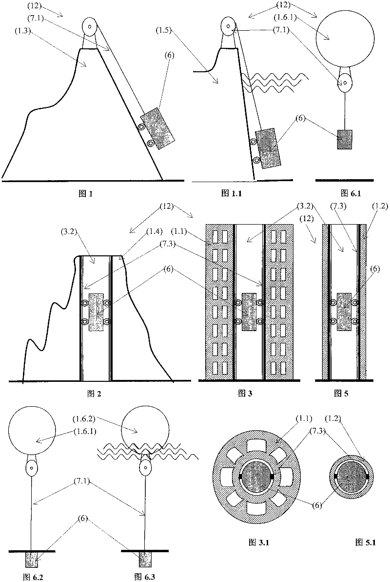
[0078] Example 1. From figure 1 It can be seen that it is a gravity storage energy device (12) arranged on the mountain body (1.3). It is characterized in that: the carrier (1)---mountain (1.3) is provided with a gravity storage energy device (12); the gravity storage energy device (12) includes the following components, the gravity body (6), the lifting gravity body device (7 ), generator device (8); lifting gravity body device (7) is rope lifting device (7.1), and the wire rope of rope lifting device (7.1) connects gravity body (6), rope lifting device (7.1) and generator device ( 8) is a shaft connection (not shown in the figure); the lifting gravity body device (7) is arranged on the mountain body (1.3); the gravity body (6) includes a solid (6.1). When the power consumption is low, the electric drive rope lifting device (7.1) pulls and lifts the gravitational body (6) from the bottom of the mountain to the top of the mountain, and stores the gravitational potential ener...
Embodiment 2
[0079] Example 2. From Figure 1.1 It can be seen that it is a gravity storage energy device (12) arranged on the ground anchor body (1.5). It is characterized in that the carrier (1) is a ground anchor body (1.5), and the gravity body (6) sinks into the water body (lake, ocean). When the power consumption is low, the electric drive rope lifting device (7.1) traction lifts the gravity body (6) from the bottom of the water body to the water body top, and stores the gravitational potential energy; 6) Pulling the rope of the rope lifting device (7.1) releases the gravitational potential energy, and the rope lifting device (7.1) drives the generator device (8) to produce electricity; the electricity supplements the peak power consumption of the power grid. All the other features and functions are the same as in Embodiment 1.
Embodiment 3
[0080] Example 3. From figure 2 It can be seen that it is a gravity storage energy device (12) arranged on the hole (1.4) of the vertical hole. It is characterized in that the carrier (1) is the entrance (1.4) of the vertical hole, and the gravity body (6) settles into the entrance of the deep hole (natural deep hole, artificial deep hole). When the power consumption is low, the electric drive rack lifting device (7.3) crawls and lifts the gravity body (6) from the bottom of the deep hole to the top of the deep hole, storing gravitational potential energy; 7.3), the gravitational body (6) pulls the rack lifting device (7.3) to release the gravitational potential energy, and the rack lifting device (7.3) drives the generator device (8) to produce electricity; the electricity supplements the peak power consumption of the power grid. All the other features and functions are the same as in Embodiment 1.
PUM
 Abstract
Description
Claims
Application Information
 - R&D
- Intellectual Property
- Life Sciences
- Materials
- Tech Scout
- Unparalleled Data Quality
- Higher Quality Content
- 60% Fewer Hallucinations
Browse by: Latest US Patents, China's latest patents, Technical Efficacy Thesaurus, Application Domain, Technology Topic, Popular Technical Reports.
© 2025 PatSnap. All rights reserved.Legal|Privacy policy|Modern Slavery Act Transparency Statement|Sitemap|About US| Contact US: help@patsnap.com


