
Double-action reciprocating hydraulic booster

A hydraulic booster, reciprocating technology, applied in the direction of fluid pressure converters, mechanical equipment, etc., can solve the problems of difficult processing, failure to achieve large flow output, easy failure of steel ball positioning, etc., to achieve simple structure, Run Reliable Effects

Inactive Publication Date: 2013-12-11
NINGBO HANSHANG HYDRAULIC
View PDF1 Cites 1 Cited by
  • Summary
  • Abstract
  • Description
  • Claims
  • Application Information

AI Technical Summary

Problems solved by technology

[0004] 1. Because the stroke reversing valve uses steel ball positioning and chains to keep it in two positions, and controls the booster cylinder to move in different directions, the structure is complicated and the processing is difficult
And the positioning of the steel ball is easy to fail, the chain is broken, and the stroke control reversing valve will be in the floating position, that is, the booster cylinder stops moving, so this control method is unreliable
[0005] 2. It adopts two-stage control of the stroke control valve and the main reversing valve. On the one hand, the structure is relatively complicated; on the other hand, it will inevitably reduce the boosting frequency of the supercharger, and the large flow output cannot be achieved.

Method used


Image

  • Double-action reciprocating hydraulic booster
  • Double-action reciprocating hydraulic booster
  • Double-action reciprocating hydraulic booster

Examples


Embodiment Construction

[0018] The present invention will be further described in detail below in conjunction with the embodiments of the drawings.

[0019] Such as Figure 1~5 Shown is a preferred embodiment of the present invention.

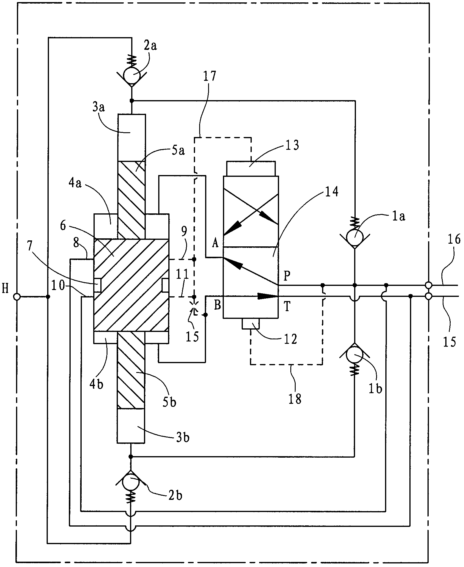
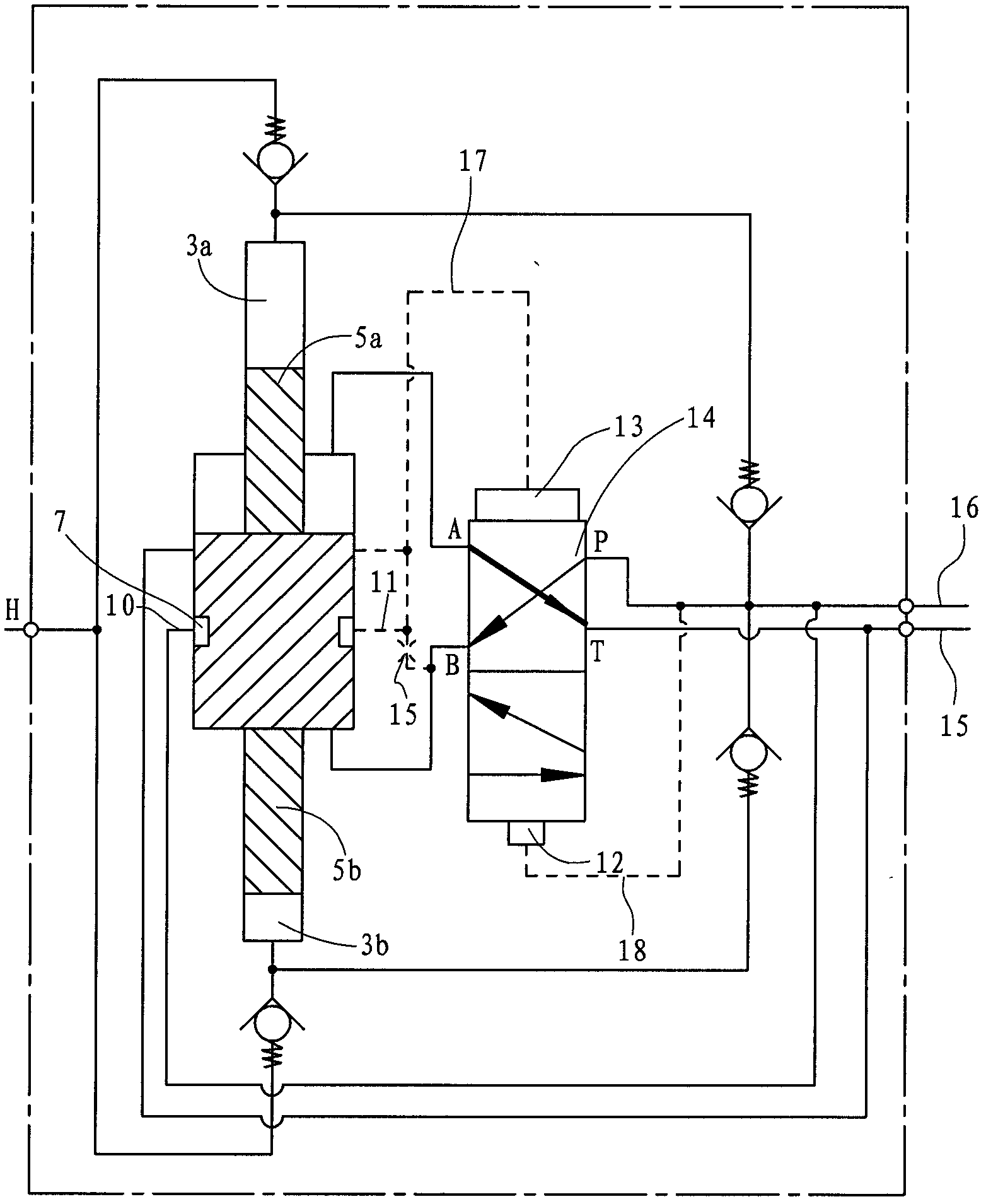
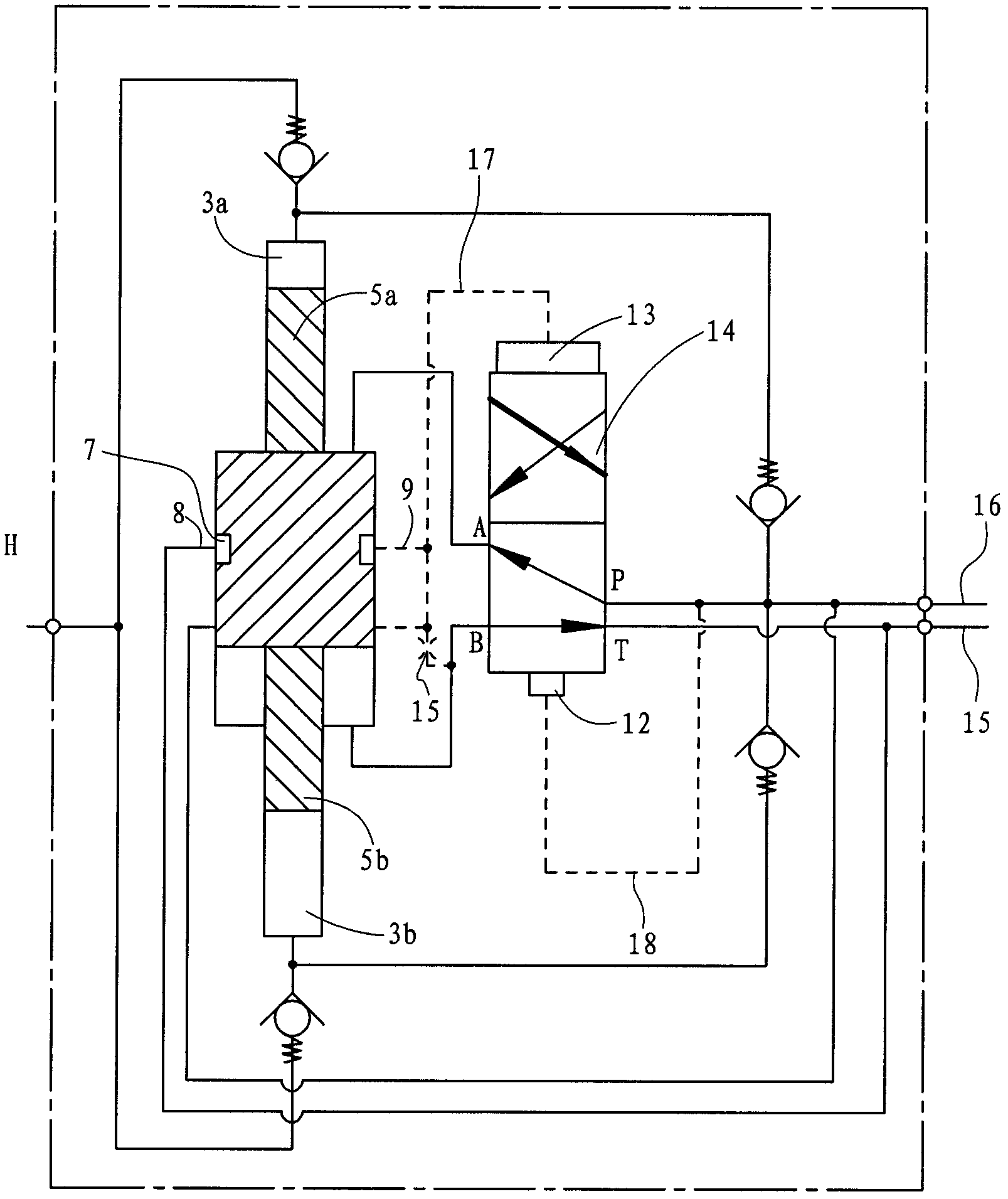
[0020] A double-acting reciprocating hydraulic pressure booster includes a pressure boosting part and an automatic reversing control valve 14. The boosting part includes a low pressure plunger 6, an upper high pressure plunger 5a and a lower high pressure plunger 5b, and an upper high pressure plunger 5a and The lower high-pressure plunger 5b is connected to the upper and lower ends of the low-pressure plunger 6, respectively, and the connection mode can refer to the background technology. An upper high pressure chamber 3a is formed above the upper high pressure plunger 5a, a lower high pressure chamber 3b is formed below the lower high pressure plunger 5b, and an upper low pressure chamber 4a and a lower low pressure chamber 4b are formed above and below the low pressure...


PUM


Abstract

The invention relates to a double-action reciprocating hydraulic booster which comprises a boosting device and an automatic reversing control valve, and is characterized in that: the upper end and the lower end of the control valve core of the automatic reversing control valve are respectively connected with an upper piston and a lower piston; the cross sectional area of the upper piston is more than that of the lower piston; a first oil port of the automatic reversing control valve is communicated with a lower low-pressure cavity, a second oil port of the automatic reversing control valve is communicated with an upper low-pressure cavity, an oil return port of the automatic reversing control valve is communicated with an oil return channel, and a high-pressure oil port of the automatic reversing control valve is communicated with a high-pressure oil channel; the boosting part is also provided with an oil inlet runner, an oil return runner, a first control runner and a second control runner; a circular communicating groove is arranged on the peripheral surface of a low-pressure plunger; and the first control runner and the second control runner are communicated with an upper chamber of the upper piston through first bypass channels. Compared with an electromagnetic reversing valve, the automatic reversing control valve has a simpler structure, is controlled with a single pole, so that the boosting frequency is not reduced, the operation is reliable, and the purpose of high-frequency boosting can be achieved.

Description

Technical field [0001] The invention relates to a supercharger, in particular to a double-acting reciprocating hydraulic supercharger capable of reliable automatic and continuous pressure. Background technique [0002] The hydraulic pressure booster is an ultra-high pressure hydraulic component that amplifies the hydraulic pressure by using the principle that the acting area at both ends of the piston is different and the force is the same. The hydraulic pressure booster can increase the low pressure to 200MPa and above. Hydraulic pressure boosters can be divided into three types: single-acting single-stroke superchargers, single-acting reciprocating superchargers and double-acting reciprocating superchargers. Since the single-acting single-stroke supercharger can only move in one direction, it is limited by the stroke and the output flow is limited. It cannot achieve continuous supercharging and has a narrow application range; the single-acting reciprocating supercharger can ach...

Claims


Application Information

Patent Timeline
Patent Type & Authority Patents(China)
IPC IPC(8): F15B3/00
Inventor 邵玉强周善舰
Owner NINGBO HANSHANG HYDRAULIC
Learn More