Controllable four-probe graphite resistance testing device

A technology of graphite resistance and testing device, applied in the field of graphite, can solve the problem of accurate value of measurement results without a fixed device, etc.

Inactive Publication Date: 2011-12-21
DATONG XINCHENG NEW MATERIAL CO LTD
View PDF4 Cites 12 Cited by
  • Summary
  • Abstract
  • Description
  • Claims
  • Application Information

AI Technical Summary

Problems solved by technology

[0003] In order to overcome the problems in the prior art that there is no fixed device and the accuracy of the measurement results is poor when measuring the graphite rod to be tested, the present invention provides a device with simple structure, convenient measurement and single-person operation, which can realize current input and voltage acquisition at any segment at the same time. value fixture

Method used


Image

  • Controllable four-probe graphite resistance testing device
  • Controllable four-probe graphite resistance testing device
  • Controllable four-probe graphite resistance testing device

Examples


Embodiment 1

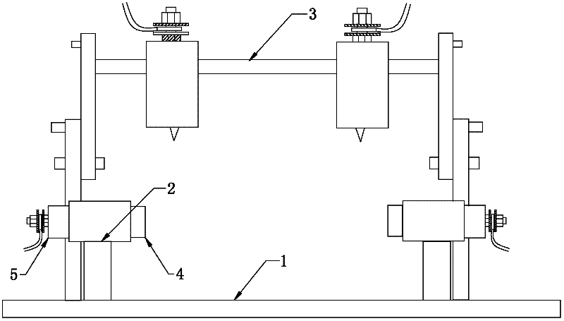
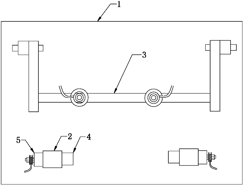
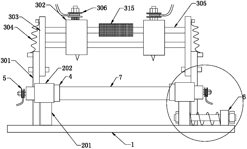
[0034] Such as figure 1 , 2As shown, the technical solution disclosed in the present invention includes a measurement platform 1 and a current measurement device 2 and a voltage measurement device 3 installed on the measurement platform, wherein the current measurement device 2 and the voltage measurement device 3 are installed side by side on the measurement platform 1, The current measurement device includes a fixed frame 201 connected to the measurement platform, a current probe base 5 and a graphite rod clamping device 4 installed on the fixed frame, and there are two fixed frames 201 located on the same axis, wherein the current probe base 5 Used to connect the two current access terminals 509 of the tester, the installation positions of the graphite rod clamping devices on the two fixed frames correspond to the graphite rod 7 to be tested, at this time the current probe base and the graphite rod to be tested The two ends are in contact to supply the measuring current fo...

Embodiment 2

[0039] Such as figure 1 , 2 , As shown in 3 and 4, on the basis of the foregoing embodiments, a fixed pipe 202 is installed on the top of the fixed frame 201 in this program, the center of the fixed pipe circle on the two fixed frames is located on the same axis, and the two ends of the fixed pipe are respectively installed The rotating tube and the current probe seat, the fixed tube 202 is provided with a retaining ring 204 with a reduced diameter, the retaining ring is used to prevent the rotating tube 401 or the current probe seat 5 from going too deep into the fixed tube, wherein the inner diameter of the rotating tube 401 is greater than or equal to the To measure the diameter of the graphite rod 7, the rotating tubes on the two fixed tubes are opposite, and the graphite rod to be measured is inserted in the two rotating tubes. The current probe base 5 includes a probe rod 502, a spring 503, a plug tube 504 and a current probe fixing device 505. The above components are ...

Embodiment 3

[0042] Such as Figure 11 As shown, in order to improve the accuracy of the angle of the graphite rod 7 to be measured when it is overturned, this solution is based on the foregoing embodiments, and an angle mark 402 is set at the nozzle of the rotating tube 401, and the angle mark is at the nozzle of the rotating tube. 90 degrees is the standard setting four, and at the same time set the reference mark 203 on the nozzle of the fixed tube 202. When rotating the graphite rod, you only need to rotate the rotating tube, and align the flip mark of the next measurement position with the reference mark, that is, the graphite to be tested is realized. The 90 standard angle flip of the rod completely avoids the flip error and improves the accuracy of the measurement results.


PUM


Abstract

The invention discloses a controllable four-probe graphite resistance testing device, which relates to the filed of graphite and comprises a measuring platform, and a current measuring device and a voltage measuring device which are arranged on the measuring platform side by side, wherein the current measuring device comprises two fixed racks, current probe seats arranged on the fixed racks, and a graphite rod clamping device, the fixed racks are on the same axis and one ends of the fixed racks are arranged on the measuring platform, the voltage measuring device comprises two stand columns fixed on the measuring platform, two support arms respectively movably arranged on the two stand columns, a voltage rotary rod for connecting the two support arms, and two voltage probe seats fixed on the voltage rotary rod. The current measuring device disclosed by the invention simultaneously realizes the current input and the clamping fixation of the graphite rod to be measured, the voltage testing device realizes the measurement of resistance at two points by the voltage rotary rod, the processes do not need to be respectively controlled manually any more, manpower and operation processes are saved, measurement errors are reduced, and the measurement precision and the measurement efficiency are improved.

Description

technical field [0001] The invention relates to the field of graphite, in particular to a testing device for testing the resistivity of graphite samples with precise positioning and simple operation. Background technique [0002] In the graphite manufacturing industry, after the graphite product is manufactured, it is necessary to measure its resistance performance to determine whether the product meets the customer's requirements. When measuring, it is necessary to pass a fixed current at both ends of the graphite rod to be tested, and then simultaneously measure on the graphite rod to be tested. Take two points to get the voltage value between the two points, and divide the voltage by the length to obtain the approximate voltage value per unit length, and then divide the unit voltage value by the fixed current to obtain the approximate resistivity per unit length. The measurement step needs to be measured four times on the circumference of the graphite rod to be tested wit...

Claims


Application Information

Patent Timeline
Patent Type & Authority Applications(China)
IPC IPC(8): G01R27/08G01R1/04
Inventor 叶荣范志利李保国赵海洋张作文宋晓明王志辉李晓静
Owner DATONG XINCHENG NEW MATERIAL CO LTD
Why Eureka
Try Eureka