Daytime running light system and control method thereof

A control method and a technology of daytime running lights, which are applied to the layout of electric lamp circuits, lighting and heating equipment, road vehicles, etc., can solve the problems of long installation lines of control modules, inconvenient installation, replacement and maintenance, etc., and achieve the reduction of installation complexity. Simple, easy-to-control effects

Inactive Publication Date: 2011-12-21
ニンボードゥジャライティングテクノロジーカンパニーリミテッド
View PDF3 Cites 0 Cited by
  • Summary
  • Abstract
  • Description
  • Claims
  • Application Information

AI Technical Summary

Problems solved by technology

However, the control module is usually integrated with the light-emitting module, and the installation position of the light-emitting module is far away from the ignition switch of the engine. Therefore, the installation line of the control module is long, and installation, replacement and maintenance are also extremely inconvenient

Method used


Image

  • Daytime running light system and control method thereof
  • Daytime running light system and control method thereof
  • Daytime running light system and control method thereof

Examples


no. 1 example

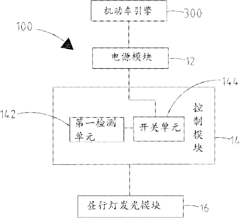
[0025] See figure 1 , the daytime running light system 100 provided by the first embodiment of the present invention includes a power supply module 12 , a control module 14 and a daytime running light light emitting module 16 . The control module 14 is electrically connected to the power module 12 and the daytime running light light emitting module 16 at the same time. The power supply module 12 is used to supply power to the control module 14 and the light emitting module 16 of the daytime running light. The power module 12 is connected to a motor vehicle engine 300 and charged by the motor vehicle engine 300 .

[0026] The working voltage of the power module 12 can be 12 volts or 6 volts. The power module 12 may include a storage battery, and the type of the storage battery is not limited, and may be a lead-acid storage battery, a lithium iron phosphate storage battery, or the like. The vehicle engine 300 may include engines of vehicles such as cars, trucks, and large veh...

no. 2 example

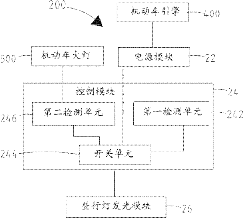
[0040] See image 3 , the daytime running light system 200 provided by the second embodiment of the present invention includes a power supply module 22 , a control module 24 and a daytime running light light emitting module 26 . The control module 24 is electrically connected to the power module 22 and the daytime running light light emitting module 26 at the same time. The power supply module 22 is used to supply power to the control module 14 and the light emitting module 26 of the daytime running light. The power supply module 22 is electrically connected to the motor vehicle engine 400 and charged through the motor vehicle engine 400 .

[0041] The control module 24 includes a first detection unit 242 , a switch unit 244 and a second detection unit 246 . The switch unit 244 is electrically connected to the power supply module 22 and the daytime running light light emitting module 26 at the same time. The first detection unit 242 is electrically connected to the switch u...


PUM


Abstract

The invention relates to a daytime running light system, which includes a power supply module, a control module and a light emitting module of the daytime running light. The power supply module is connected with a motor vehicle engine, and the motor vehicle engine generates continuous electric sparks when running. The control module includes a first detection unit and a switch unit, and the switch unit is electrically connected to the power supply module and the daytime running light lighting module at the same time. The first detection unit is electrically connected to the switch unit. The first detection unit detects the electromagnetic wave emitted by the electric spark and closes or disconnects the switch unit according to the detection result. The invention also relates to a control method of the daytime running light system. Adopting the technical scheme of the invention, the installation and control are relatively simple.

Description

technical field [0001] The invention relates to the field of vehicle light control, in particular to a daytime running light system and a control method thereof. Background technique [0002] Daytime Running Light (DRL, Daytime Running Light) is a special lamp that can be turned on automatically when the motor vehicle is started. It is very energy-saving, and the power consumption is only 25% to 30% of that of ordinary car lights. In order to increase road safety, the European Union has introduced ECER87 regulations for daytime running lights. According to the regulations, all new motor vehicles in the EU, including cars, trucks and large vehicles, need to install special daytime running lights to increase the visibility of daytime driving and reduce the probability of traffic accidents. [0003] The existing daytime running light system usually includes a light emitting module and a control module. The control module is electrically connected with the ignition switch of ...

Claims


Application Information

Patent Timeline
Patent Type & Authority Applications(China)
IPC IPC(8): H05B37/02F21S8/10F21W101/02F21Y101/02F21W107/10
Inventor 刘学勇
Owner ニンボードゥジャライティングテクノロジーカンパニーリミテッド
Why Eureka
Try Eureka