
Pixel driving circuit and driving method thereof, and display panel

A pixel drive circuit and resistor technology, applied in static indicators, instruments, etc., can solve problems such as large changes in chromaticity-current curves, chromaticity changes, chromaticity changes, etc.

Active Publication Date: 2021-04-30
XIAMEN TIANMA MICRO ELECTRONICS
View PDF0 Cites 0 Cited by
  • Summary
  • Abstract
  • Description
  • Claims
  • Application Information

AI Technical Summary

Problems solved by technology

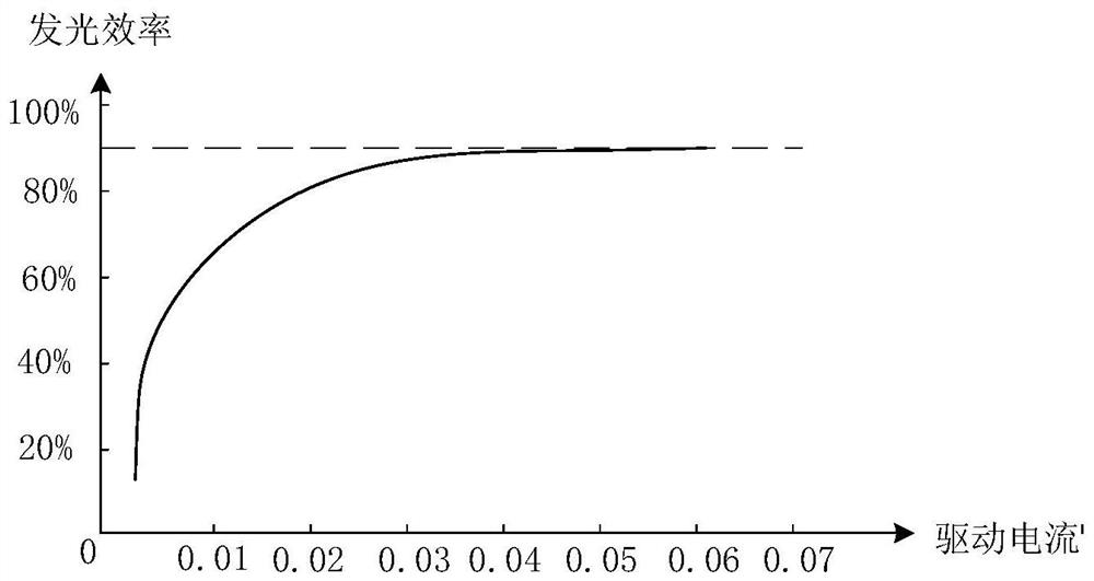
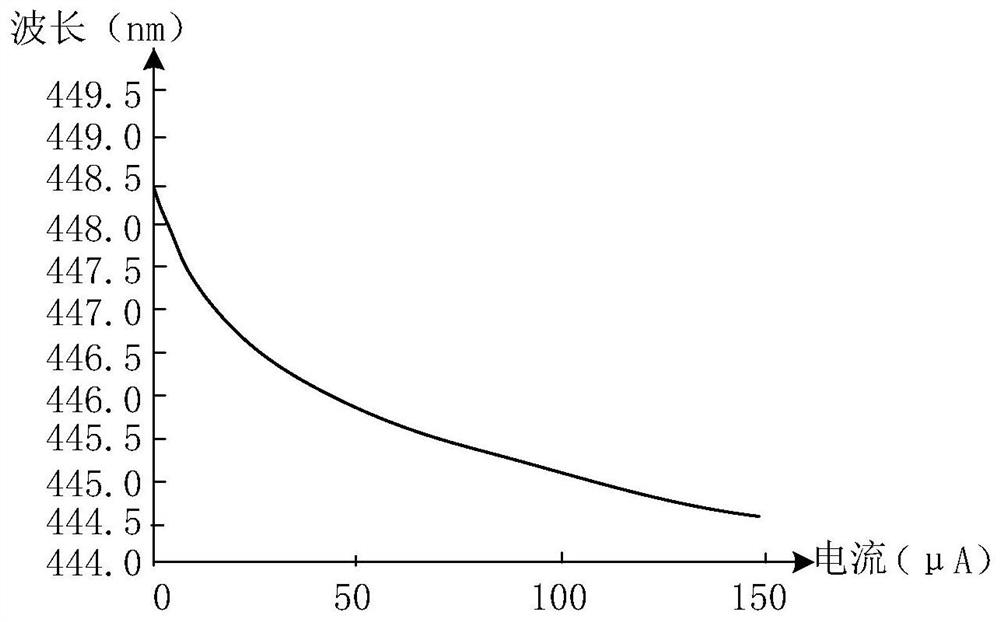
However, when the traditional drive circuit is applied to the Micro LED display panel, the chromaticity-current curve of the LED changes greatly, and a weak current change will cause a change in chromaticity detectable by the human eye.
Therefore, if a Micro LED panel adopts a traditional driving circuit, it is inevitable that there will be a problem of chromaticity change under different gray scales.
[0004] During the implementation process, the inventors found that there are at least the following problems in the traditional technology: using the traditional drive circuit to control the brightness with current, it is inevitable that there will be a problem of chromaticity changes under different gray scales

Method used


Image

  • Pixel driving circuit and driving method thereof, and display panel
  • Pixel driving circuit and driving method thereof, and display panel
  • Pixel driving circuit and driving method thereof, and display panel

Examples


Embodiment Construction

[0040] Various exemplary embodiments of the present invention will now be described in detail with reference to the accompanying drawings. It should be noted that the relative arrangements of components and steps, numerical expressions and numerical values ​​set forth in these embodiments do not limit the scope of the present invention unless specifically stated otherwise.

[0041] The following description of at least one exemplary embodiment is merely illustrative in nature and in no way taken as limiting the invention, its application or uses.

[0042] Techniques, methods and devices known to those of ordinary skill in the relevant art may not be discussed in detail, but where appropriate, techniques, methods and devices should be considered part of the description.

[0043] In all examples shown and discussed herein, any specific values ​​should be construed as exemplary only, and not as limitations. Therefore, other instances of the exemplary embodiment may have differen...


PUM


Abstract

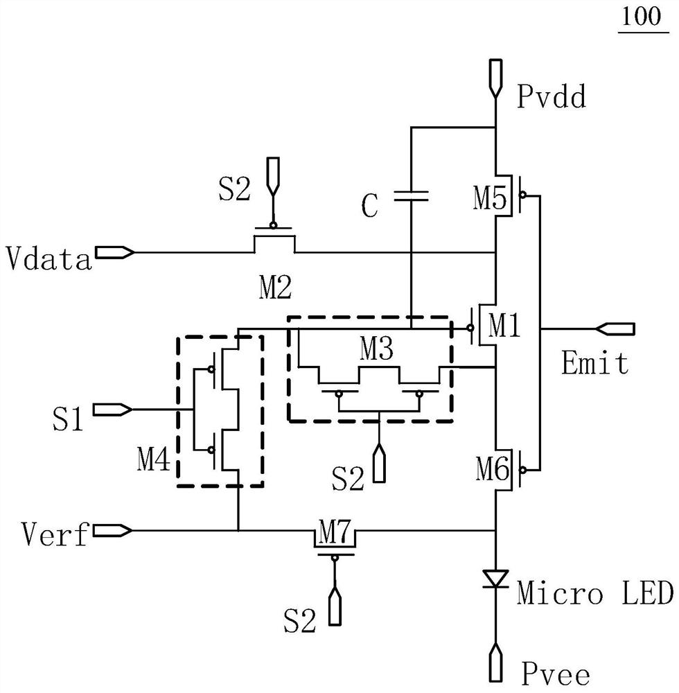
The invention discloses a pixel driving circuit, a driving method thereof, and a display panel. The pixel driving circuit includes: a data writing module, used to transmit a data signal voltage to an oscillator module in response to a current scanning signal; an oscillator module, used for According to the data signal voltage transmitted by the data writing module, a square wave signal is generated to the light emitting module, and the proportion of the first signal holding time of the square wave signal is adjusted at the same time; the light emitting module is used to emit light in response to the first signal of the square wave signal. The pixel driving circuit, its driving method, and the display panel provided by the present invention can generate a square wave signal through an oscillator module, and can control the duty ratio of the square wave signal at the same time, thereby improving the luminous efficiency of the light emitting module.

Description

technical field [0001] The present invention relates to the field of display technology, and more specifically, to a pixel driving circuit, a driving method thereof, and a display panel. Background technique [0002] Micro Light Emitting Diode (English: Micro Light Emitting Diode, Micro-LED for short) display panels are widely considered by the industry to be an important development direction of future display technology due to their low driving voltage and long lifespan. [0003] Existing pixel driving circuits generally adopt a 7T1C structure (7 thin film transistors and 1 capacitor), and use voltage to control the gate-source current of the Driving TFT (driving TFT) to emit light, and its luminous brightness depends on the magnitude of the gate-source current. However, when the traditional driving circuit is applied to the Micro LED display panel, the chromaticity-current curve of the LED changes greatly, and a weak current change will cause a change in chromaticity that...

Claims


Application Information

Patent Timeline
Patent Type & Authority Patents(China)
IPC IPC(8): G09G3/32
CPCG09G3/32G09G2320/0626
Inventor 王婷伍黄尧周洪波
Owner XIAMEN TIANMA MICRO ELECTRONICS
Learn More