Eureka AIR delivers breakthrough ideas for toughest innovation challenges, trusted by R&D personnel around the world.

The Arrangement Structure of the Stabilizer on the Motor Wheel Suspension Structure

A technology for layout structure and wheel suspension, which is applied in the direction of suspension, elastic suspension, vehicle spring, etc. It can solve the problems of complex assembly process of stabilizer and thermal load of stabilizer that damages working ability, etc.

Inactive Publication Date: 2011-12-21
AUDI AG
View PDF4 Cites 8 Cited by
  • Summary
  • Abstract
  • Description
  • Claims
  • Application Information

AI Technical Summary

Problems solved by technology

On the one hand, the stabilizer is subjected to thermal loads during driving that can impair its working capacity
On the other hand, the assembly process of removing the stabilizer from the vehicle in the case of after-sales service is complicated

Method used


Image

  • The Arrangement Structure of the Stabilizer on the Motor Wheel Suspension Structure
  • The Arrangement Structure of the Stabilizer on the Motor Wheel Suspension Structure
  • The Arrangement Structure of the Stabilizer on the Motor Wheel Suspension Structure

Examples


Embodiment Construction

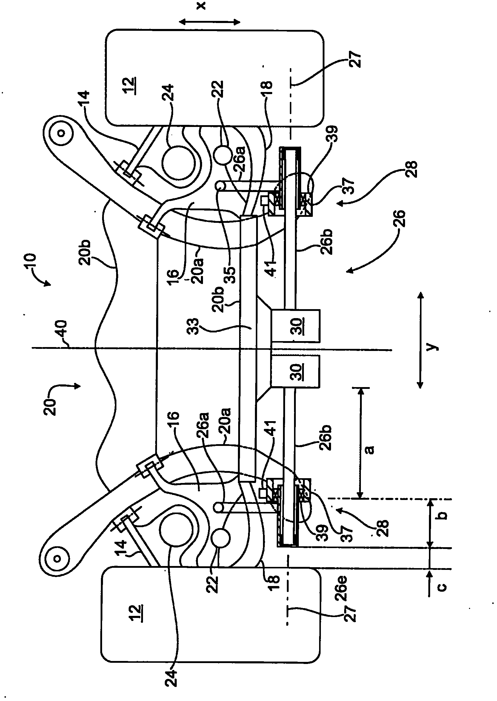
[0016] figure 1 Roughly schematically shows a rear wheel suspension 10 for a rear wheel 12 of a motor vehicle, wherein control arms 14 , 16 , 18 , not shown in detail, guiding the wheel, are articulated on the wheel side in a pivotable manner to the hub carrier frame (not visible), and hinged on the auxiliary frame 20 in a swingable manner on the vehicle body side. As can be seen, the subframe 20 has two longitudinal supports 20a and two transverse supports 20b and is fastened in a manner not shown to the motor vehicle body via a vibration-damping support structure.

[0017] In addition, a damper 22 and a support spring 24 are respectively arranged in known manner between the control arms 14 , 18 and the vehicle body. The wheel suspension 10 can also be designed in a modified form as a wheel suspension for front steered wheels of a motor vehicle.

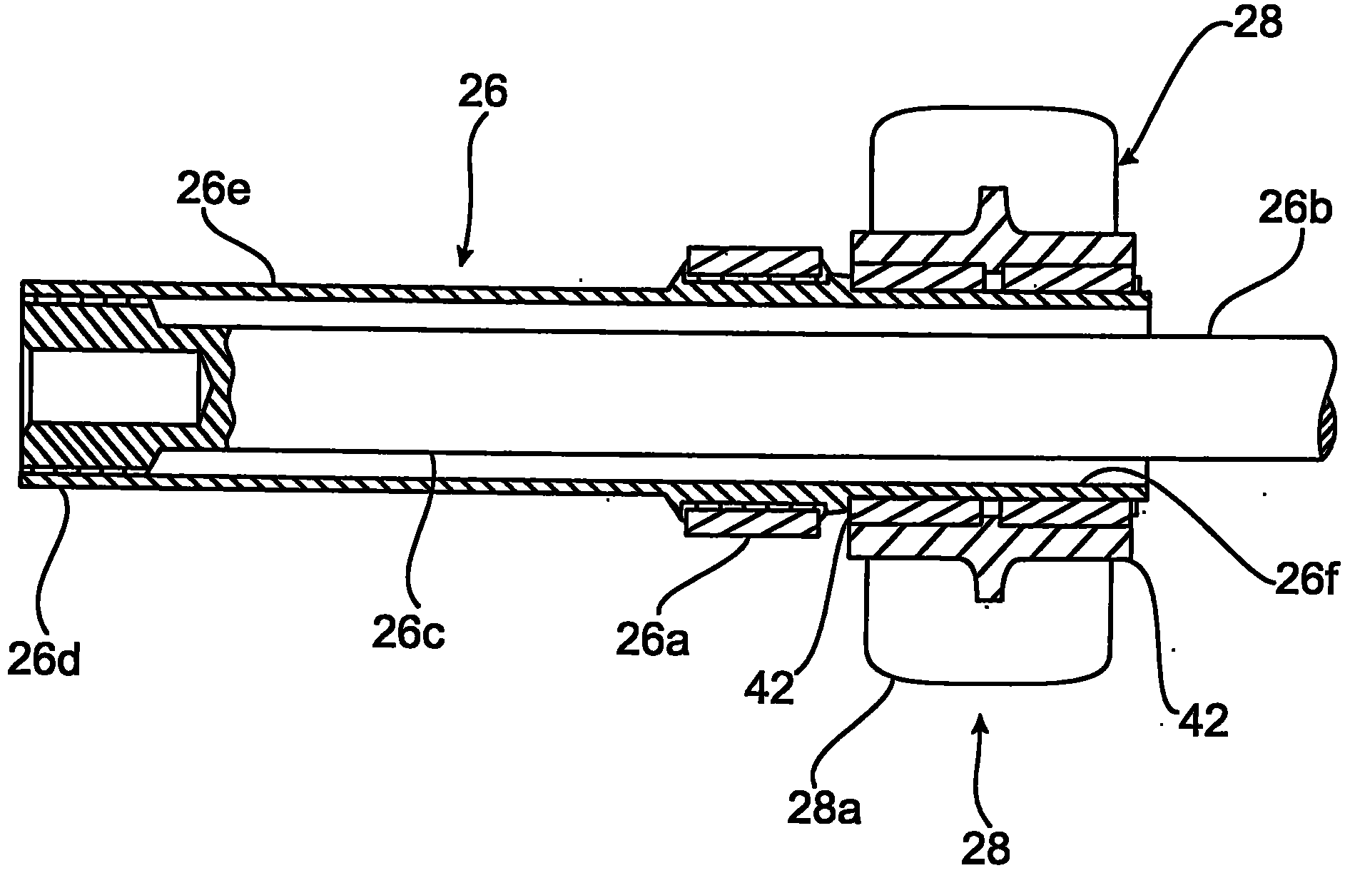
[0018] In addition according to figure 1 , a substantially U-shaped two-piece stabilizer 26 is rotatably supported on the wheel...


PUM


Abstract

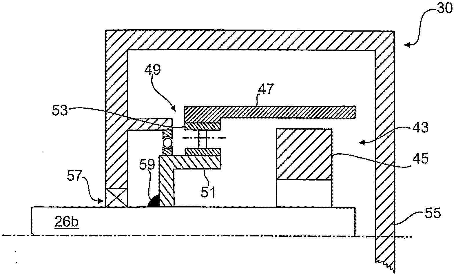
The invention relates to the arrangement of a two-part stabilizer (26) on a motor vehicle wheel suspension structure, including torsion bars (26b) designed to be separated from each other and each of which is articulated via a transmission rod (26a). On the wheel suspension element (16), the torsion bars can be rotated in the same direction or opposite to each other by means of a respective adjustment device (30), wherein in order to lengthen the effective torsion length of the respective torsion bar (26b), a respective adjustment device (30) is used. A hollow shaft (26e) surrounding the torsion bar (26b) lengthens the torsion bar, and the transmission rod (26a) is arranged on the hollow shaft. According to the invention, the torsion bar (26b) is supported in the adjusting device (30) via a fixed support structure (59) and in the hollow shaft (26e) via an axially floating support structure (26d).

Description

technical field [0001] The invention relates to an arrangement of a stabilizer on a wheel suspension structure of a motor vehicle according to the preamble of claim 1 . Background technique [0002] For example, DE 101 26 928 A1, DE 10 2004 002 550 A1 or DE 102 42 552 B4 disclose two-part stabilizer arrangements of this type with adjustment devices for controlling the spring stiffness and driving behavior of the motor vehicle. In this case, the roll behavior (performance) or the cornering inclination of the motor vehicle can be reduced by adjusting the separate torsion bars of the generally U-shaped stabilizer in the opposite direction, or by adjusting in the same direction against the pitch inclination, for example when braking . [0003] From DE 10 2007 007 214 A1 an arrangement of a two-part stabilizer on a motor vehicle wheel suspension is known. This stabilizer has separate torsion bars which are each articulated via a drive link to the wheel suspension element and wh...

Claims


Application Information

Patent Timeline
Patent Type & Authority Applications(China)
IPC IPC(8): B60G21/055B60G17/02B60G11/18B60G17/016
CPCB60G2204/418B60G11/183B60G2206/8201B60G2204/4232B60G2204/44B60G2206/427B60G2202/42B60G17/0162B60G2204/1222B60G21/0555B60G17/025B60G2206/8207B60G2204/45B60G2206/82B60G2200/184
Inventor A·奥力士W·施密特
Owner AUDI AG
Why Eureka
Eureka Blog
Learn More