Boring and Rolling Compound Tool

A compound cutting tool and boring tool technology, which is applied in the direction of cutting tools used in lathes, manufacturing tools, tool holder accessories, etc., can solve the problems of not having a guiding function and failing to meet tolerance requirements, and achieve short auxiliary time and high production efficiency , the effect of process concentration

Active Publication Date: 2011-12-28
宁波市精恒凯翔机械有限公司
View PDF6 Cites 3 Cited by
  • Summary
  • Abstract
  • Description
  • Claims
  • Application Information

AI Technical Summary

Problems solved by technology

In this design, a hydraulic steel ball structure is arranged at the rear end of the boring tool. At the rear of the boring process, the steel ball realizes the secondary rolling processing of the inner wall surface of the boring. Structurally, the steel ball only runs along the feed path of the original cutter bar, and it has no guiding function; the secondary rolling function of the steel ball is limited to simple deburring of the surface after boring, and cannot meet the specific tolerance requirements.

Method used


Image

  • Boring and Rolling Compound Tool
  • Boring and Rolling Compound Tool
  • Boring and Rolling Compound Tool

Examples


Embodiment Construction

[0025] The present invention will be further described in detail below in conjunction with the accompanying drawings and embodiments.

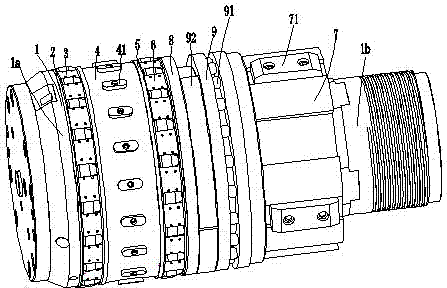
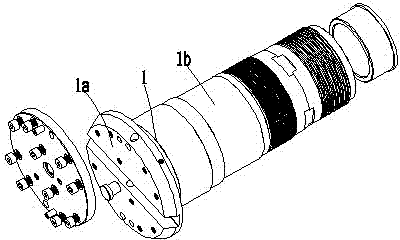
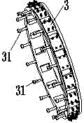
[0026] Such as Figure 1 to Figure 9 As shown, the symbol numbers are explained as follows: mandrel 1, cutterhead body 1a, shaft extension cylinder 1b, front raceway 2, front retainer 3, first connecting screw 31, middle sleeve 4, first guide block 41, rear Raceway 5, rear retainer 6, support sleeve 7, second guide block 71, distance sleeve 8, bearing sleeve 81, seat cushion 9, second connecting screw 91, semicircle adjustment pad 92.

[0027] In the embodiment of the present invention, the boring-rolling compound tool includes a rolling part and a boring tool part. The boring tool part includes a mandrel 1. The front end of the mandrel 1 is formed with a cutter body 1a equipped with a boring tool. The shaft extension cylinder 1b; the rolling part includes the front raceway 2, the front cage 3, the middle sleeve 4, the rear raceway 5 and the ...


PUM


Abstract

The invention discloses a boring and rolling combined cutting tool, which comprises a rolling part and a boring cutter part, wherein the boring cutter part comprises a core shaft, the front end of the core shaft is provided with a cutterhead body for assembling a boring cutter, and the rear end of the core shaft is provided with a circular shaft extending cylinder; the rolling part comprises a front raceway, a front retainer, a middle sleeve, a rear raceway and a rear retainer which are sequentially arranged, and the front raceway, the front retainer, the middle sleeve, the rear raceway and the rear retainer are all matched with a front outer ring of the shaft extending cylinder in a buckle mode; the middle part of the shaft extending cylinder is connected with a supporting sleeve in a screwed mode, and the front raceway, the front retainer, the middle sleeve, the rear raceway and the rear retainer are controlled to be fixed in the axial position on the front outer ring of the shaft extending cylinder by the screwed supporting sleeve; in rolling processing, a rolling tool applies certain pressure on the surface of a workpiece, and microcosmic crests and microcosmic troughs originally remained on the surface of the workpiece are rolled to be flat to reduce surface roughness; in boring and rolling combined rolling, the boring process and the rolling process are combined to make boring more stable; and the assisting time is short, and the production efficiency is high.

Description

technical field [0001] The invention relates to the technical field of metal cutting tools, in particular to a boring and rolling compound tool. Background technique [0002] Generally, the boring machine tool with traditional structure includes a boring tool and a tool bar. The boring tool is installed on the tool bar, and the boring machine spindle is used to drive the tool bar and the boring tool to rotate, that is, to realize the boring processing of the workpiece; so the traditional boring tool only has cutting functions. It does not have the function of secondary processing on the inner wall of the boring hole, and is especially not suitable for workpieces with high requirements on the hole wall. [0003] In the prior art, the structure of the boring-rolling compound cutter is such as the Chinese invention patent "A Novel Rolling Function Boring Bar" (the announcement number is CN201776462U) whose patent number is CN201020179702.8; The through hole is connected with t...

Claims


Application Information

Patent Timeline
Patent Type & Authority Applications(China)
IPC IPC(8): B23B27/00
Inventor 李龙江
Owner 宁波市精恒凯翔机械有限公司
Why Eureka
Try Eureka