Stamping punching die

A technology of mold and mold holder, which is applied in the direction of perforating tools, manufacturing tools, metal processing, etc., can solve problems such as batch processing troubles, and achieve the effect of batch processing convenience

Inactive Publication Date: 2011-12-28
WUJIANG WUGANG PUNCHING MACHINERY
View PDF6 Cites 9 Cited by
  • Summary
  • Abstract
  • Description
  • Claims
  • Application Information

AI Technical Summary

Problems solved by technology

[0002] In the prior art, the holes on the workpiece are usually proc

Method used


Image

  • Stamping punching die
  • Stamping punching die
  • Stamping punching die

Examples


Example Embodiment

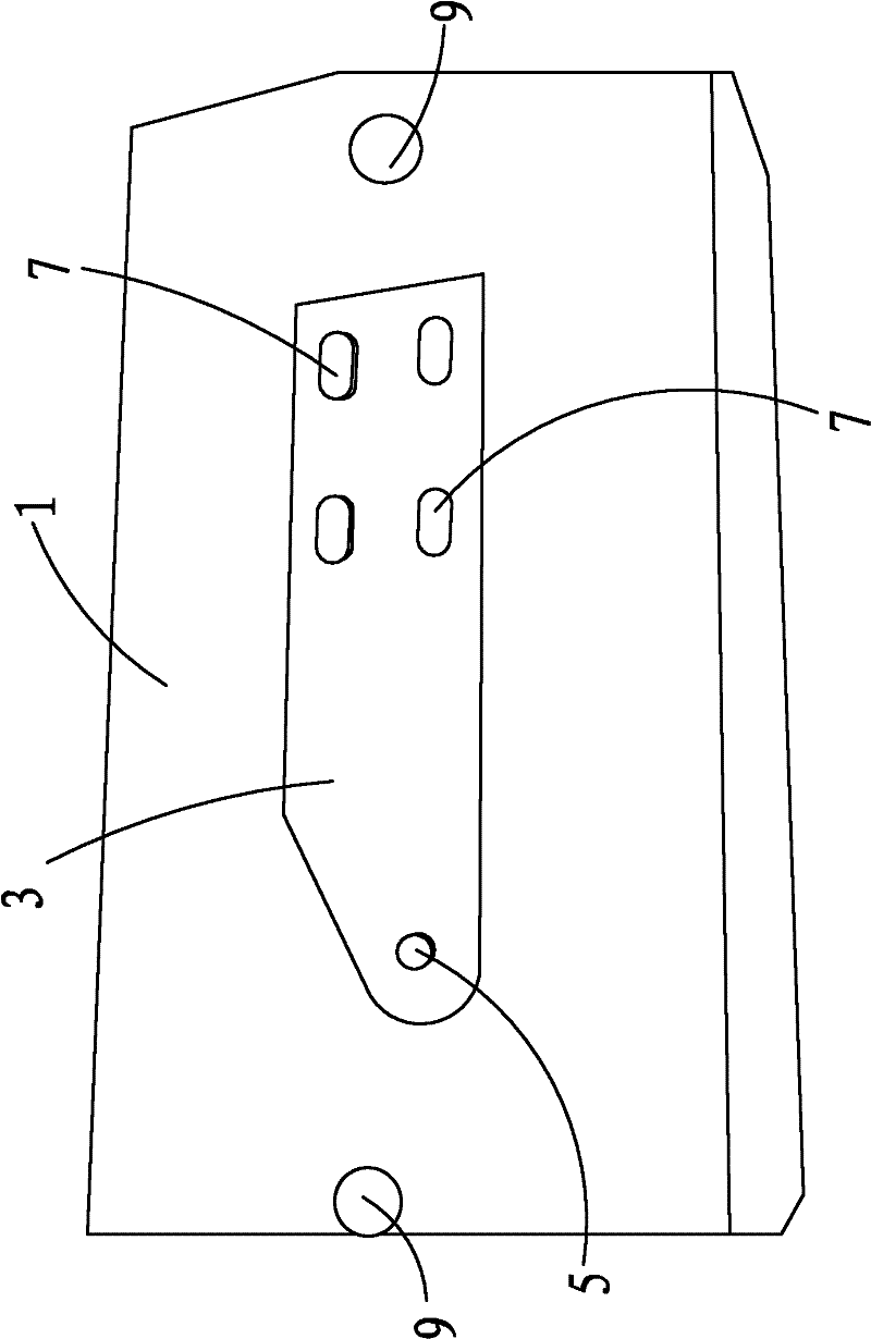
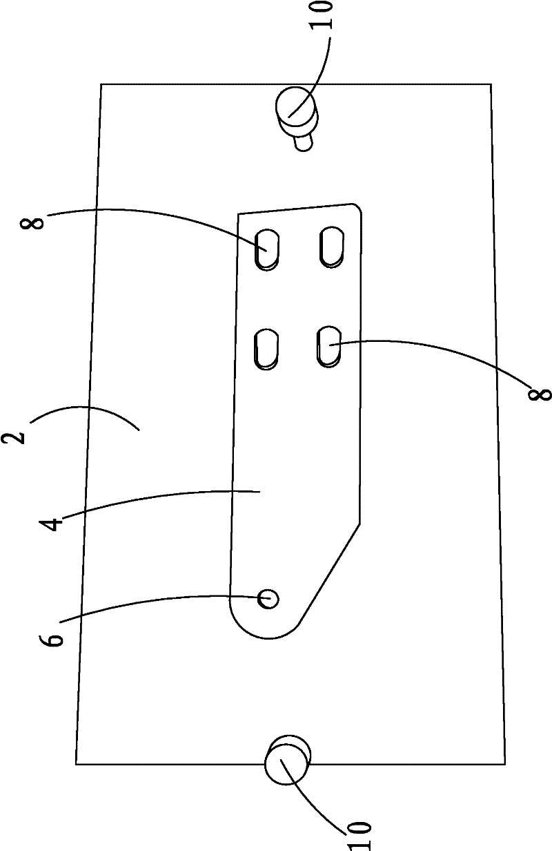
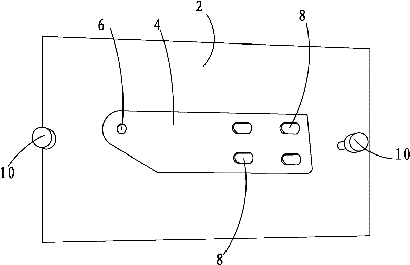
[0014] as attached figure 1 -Attached figure 2 As shown, a punching die includes an upper die seat 1, a lower die seat 2 matched with the upper die seat 1, the upper die seat 1 is provided with an upper mold hole 3, and the The lower mold base 2 is provided with a lower mold hole 4, and the upper mold hole 3 and the lower mold hole 4 form a receiving cavity for accommodating the workpiece to be processed. The upper mold hole 3 and the lower mold hole 4 One of the two is provided with a processing hole, the other of the two is provided with a processing protrusion, and the processing hole corresponds to the processing protrusion one-to-one.

[0015] The machining holes include circular holes 5 , and the machining protrusions include circular protrusions 6 . During machining, the circular protrusions 6 are inserted into the circular holes 5 .

[0016] The machining hole includes an elongated hole 7 , and the machining protrusion includes an elongated protrusion 8 . Du...


PUM


Abstract

A stamping and punching die, comprising an upper die seat and a lower die seat matched with the upper die seat, the upper die seat is provided with an upper model hole, and the lower die seat is provided with a lower die seat Holes, the upper mold hole and the lower mold hole form a storage cavity for receiving processed workpieces, one of the upper mold hole and the lower mold hole is provided with a machining hole, and The other has processing protrusions, and the processing holes correspond to the processing protrusions one by one. Through the cooperation of the processing protrusion and the processing hole, holes can be drilled at the corresponding parts of the processing workpiece, and batch processing is more convenient.

Description

technical field [0001] The invention relates to a stamping and punching die. Background technique [0002] In the prior art, holes on workpieces are usually processed by boring or turning, which is cumbersome for batch processing. Contents of the invention [0003] The technical problem to be solved by the present invention is to provide a stamping and punching die. [0004] In order to solve the above-mentioned technical problems, a technical solution adopted by the present invention is: a stamping and punching die, including an upper die seat, a lower die seat matched with the upper die seat, and a There is an upper mold hole, and the lower mold seat is provided with a lower mold hole, and the upper mold hole and the lower mold hole form a storage cavity for accommodating workpieces, the upper mold hole, the lower mold hole One of the two model holes is provided with a processing hole, and the other of the two is provided with a processing protrusion, and the processin...

Claims


Application Information

Patent Timeline
IPC IPC(8): B26F1/14B21D28/34
Inventor 吴小刚
Owner WUJIANG WUGANG PUNCHING MACHINERY
Why Eureka
Try Eureka