Processing technique of Roots blower impeller component

A Roots blower and processing technology, applied in the fan field, can solve problems such as low efficiency, affecting the normal operation of the fan, and low overall efficiency of the fan

Inactive Publication Date: 2011-08-17
常州市风机制造有限公司
View PDF5 Cites 4 Cited by
  • Summary
  • Abstract
  • Description
  • Claims
  • Application Information

AI Technical Summary

Problems solved by technology

[0002] The impeller on each impeller shaft of the existing Roots blower is integral, and its impeller shape is usually processed by CNC planing. The processing accuracy is poor and the surface finish is not high, making the overall efficiency of the fan low. When the medium contains certain impurities, the impurities are easily adsorbed and adhered to the surface of the impeller, which affects the normal operation of the fan.
[0003] Generally, slotting machine can be used to process the keyway of the impeller, but this method is suitable for processing the keyway of the whole impeller, but for the keyway processed by the multi-piece and combined impeller slotting machine, the repeatability is poor, and the error between each impeller is relatively large, which gives Assembly is difficult, because wire cutting is used to process key grooves, if the positioning is accurate, the processed key grooves have good repeatability, which is conducive to assembly. Therefore, most of the impeller key grooves are processed by wire cutting now, but how to ensure accurate positioning according to the shape of the impeller, It is a very troublesome thing, every time you need to play the watch, correct the positioning, even if the efficiency is not high, the processing accuracy is not ideal, which directly affects the output and quality of production

Method used


Image

  • Processing technique of Roots blower impeller component
  • Processing technique of Roots blower impeller component
  • Processing technique of Roots blower impeller component

Examples


Embodiment Construction

[0041] The following embodiments are given in conjunction with the accompanying drawings to further describe in detail the processing technology of the Roots blower impeller assembly of the present invention.

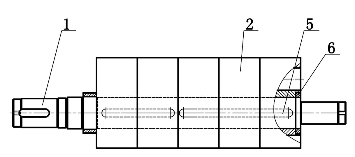
[0042] see figure 1 , the processing technology of the Roots blower impeller assembly. The impeller assembly is composed of a plurality of impeller blades 2 pressed by a special press, positioned and pressed with the positioning key 5, positioned and pressed on the impeller shaft 1, and then tightened by the lock nut 6. Specifically, Including the following process steps:

[0043] (1). The impeller shaft ( 1 ) is round steel blanking. After rough turning, it is quenched and tempered, and then it is fine turned, and the keyway and locking gasket groove are milled to meet the design requirements;

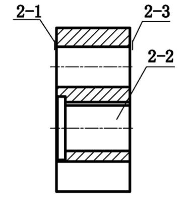
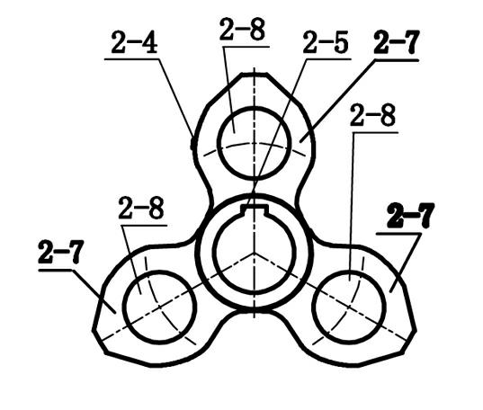
[0044] (2). Processing of impeller blade 2: see figure 2 , 3 ,

[0045] a. Cast the blank of the impeller blade 2 according to the figure and then perform annealing treatm...


PUM

PropertyMeasurementUnit
angleaaaaaaaaaa

Abstract

The invention provides a processing technique of a Roots blower impeller component. The impeller component is formed by positioning and pressing a plurality of impeller blades with positioning keys by a special pressing machine on an impeller shaft, stacking the impeller blades and then fixing and combining the impeller blades by locking nuts; each impeller blade is processed by processing steps of casting, annealing, turning, grinding, polishing, milling, linear cutting, boring and the like; the contour of each impeller blade is finished by the finish machining of a milling machine tooling on a numerical control milling machine; and a positioning key groove of each impeller blade is cut by a second tooling on an electric spark wire cutting machine, so that the axial hole positioning key grooves of all the impeller blades are accurate and consistent in position. Therefore, the finished impeller component processed by the processing technique disclosed by the invention has high accuracy, good surface quality and good interchangeability; after the impeller component is arranged in an inner cavity of the blower, all assembling gaps at different positions can be controlled in a smaller range, and the leakage rate is reduced, so that the temperature rise of gas at an outlet is lower, further the efficiency of a blower is improved and the energy is saved.

Description

technical field [0001] The invention relates to the technical field of fans, in particular to a processing technology of a Roots blower impeller assembly. Background technique [0002] The impeller on each impeller shaft of the existing Roots blower is integral, and its impeller shape is usually processed by CNC planing. The processing accuracy is poor and the surface finish is not high, making the overall efficiency of the fan low. When the medium contains certain impurities, the impurities are easily adsorbed and adhered to the surface of the impeller, which affects the normal operation of the fan. [0003] Generally, slotting machine can be used to process the keyway of the impeller, but this method is suitable for processing the keyway of the whole impeller, but for the keyway processed by the multi-piece and combined impeller slotting machine, the repeatability is poor, and the error between each impeller is relatively large, which gives Assembly is difficult, because ...

Claims


Application Information

Patent Timeline
Patent Type & Authority Applications(China)
IPC IPC(8): B23P15/00
Inventor 巢伯新
Owner 常州市风机制造有限公司
Why Eureka
Try Eureka