Roller slope control device

A technology for controlling device and wheel inclination, which is applied in transportation and packaging, winding strips, thin material processing, etc., and can solve problems affecting the processing of working links, material belt damage, uneven pressure, etc.

Inactive Publication Date: 2011-12-28
唐虎
View PDF3 Cites 5 Cited by
  • Summary
  • Abstract
  • Description
  • Claims
  • Application Information

AI Technical Summary

Problems solved by technology

The general driven roller will run along with the material belt when it receives the winding force of the material belt, but the pressure of the roller itself will be uneven, so after the material belt is transported for a certain period of time, it will be on the roller. Deflection o

Method used


Image

  • Roller slope control device
  • Roller slope control device

Examples


Embodiment Construction

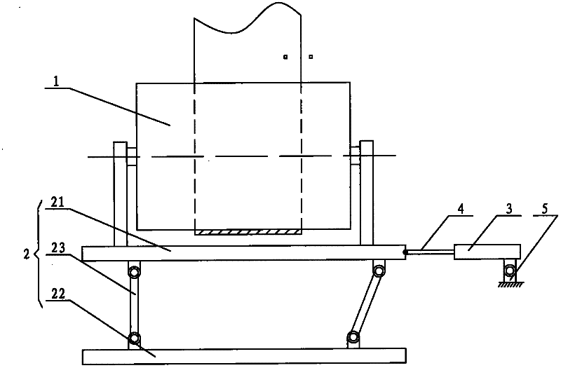
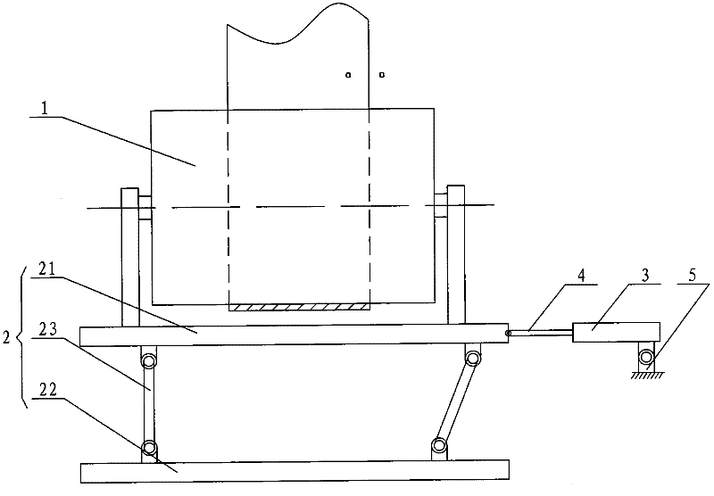
[0014] Such as figure 1 As shown, the roller inclination control device according to the present invention mainly includes a roller 1, an inclination control mechanism 2 and a driving cylinder 3. However, the roller 1 plays a supporting role on the material belt, and the roller shafts at the centers of the two ends of the roller 1 are respectively installed on the upper bracket of the tilt control mechanism 2, and the bracket is installed upright on the upper surface of the tilt control structure 2 and For fixing, the movable end of the tilt control mechanism 2 is affixed to the piston rod 4 of the drive cylinder 3, and the position of the drive cylinder 3 itself is fixed; the tilt control mechanism 2 includes an upper panel 21 and a lower base plate 22, and the lower base plate 22 is fixed in position, and the upper panel 21 is a movable plate. Two support plates 23 are supported between the upper panel 21 and the lower base plate 22. Hinged, the upper panel 21 , the lower b...


PUM


Abstract

The roller inclination control device mainly includes a roller, an inclination control mechanism and a driving cylinder. The roller is installed on the inclination control mechanism, and the roller supports the material belt. On the bracket at the top of the tilt control mechanism, the bracket is installed upright on the upper surface of the tilt control structure and fixed, and the movable end of the tilt control mechanism is fixedly connected with the piston rod of the driving cylinder; the tilt control mechanism includes The upper panel and the lower base plate, the position of the lower base plate is fixed, and the upper panel is a movable plate; the piston rod of the driving cylinder is connected to the side of the upper panel. Through the roller inclination control device designed above, the piston rod of the driving cylinder can drive the upper panel to move left and right. During the movement of the upper panel, the upper panel will deflect in the horizontal direction driven by the two hinged support plates. , and then control the force of the tape on the roller, and finally adjust the position of the tape on the roller.

Description

technical field [0001] The invention relates to a roller inclination control device, which is applied to various industries involving material belt transmission. Background technique [0002] At present, many kinds of material belts are arranged in rolls. During the process of opening or winding the material belts, rollers are needed for transmission. The material belts are erected on the rollers, and the material belts are driven forward by the axles of the rollers, or the material belts In the process of advancing, the rollers are driven to run. Therefore, in the process of use, the rollers are divided into driving rollers and driven rollers. The general driven roller will run along with the material belt when it receives the winding force of the material belt, but the pressure of the roller itself will be uneven, so after the material belt is transported for a certain period of time, it will be on the roller. Deflection occurs, and if the deflection is too large, it is ...

Claims


Application Information

Patent Timeline
IPC IPC(8): B65H23/038
Inventor 唐虎
Owner 唐虎
Why Eureka
Try Eureka