
Limiting device and method of lifting and pushing mechanism of mine excavator

A technology for excavators and mines, which is applied in the field of limit devices, can solve the problems that affect the life of equipment mechanisms, only have mechanical baffles, and the accuracy cannot meet the requirements, etc., and achieve the effect of meeting urgent needs, accurate and flexible setting

Active Publication Date: 2013-05-22
TAIYUAN HEAVY IND
View PDF5 Cites 0 Cited by
  • Summary
  • Abstract
  • Description
  • Claims
  • Application Information

AI Technical Summary

Problems solved by technology

[0002] At present, mining excavators are mainly used for mining in open-pit mines. The excavators vibrate greatly when they work. The lifting and pushing mechanisms of domestic excavators WK-4 and WK-10 are not equipped with electrical limit devices. The hoisting mechanism of the excavator has no limit, and there are often phenomena such as collision with the sky wheel or excessive lifting and lowering, and the hoisting rope falling out of the groove; The finale is broken, which affects the life of the equipment mechanism
In addition, in order to meet the excavation process requirements of large excavators, it is necessary to set multiple pre-limits. Using collision limit switches requires a large number and is very inconvenient to install. Using traditional rotation limit switches, due to the different sizes of buckets, the limit different points, the adjustment is very difficult, and the accuracy cannot meet the requirements. Large excavators urgently need an effective limit

Method used


Image

  • Limiting device and method of lifting and pushing mechanism of mine excavator
  • Limiting device and method of lifting and pushing mechanism of mine excavator
  • Limiting device and method of lifting and pushing mechanism of mine excavator

Examples


Embodiment Construction

[0018] The present invention will be further explained below in conjunction with the drawings.

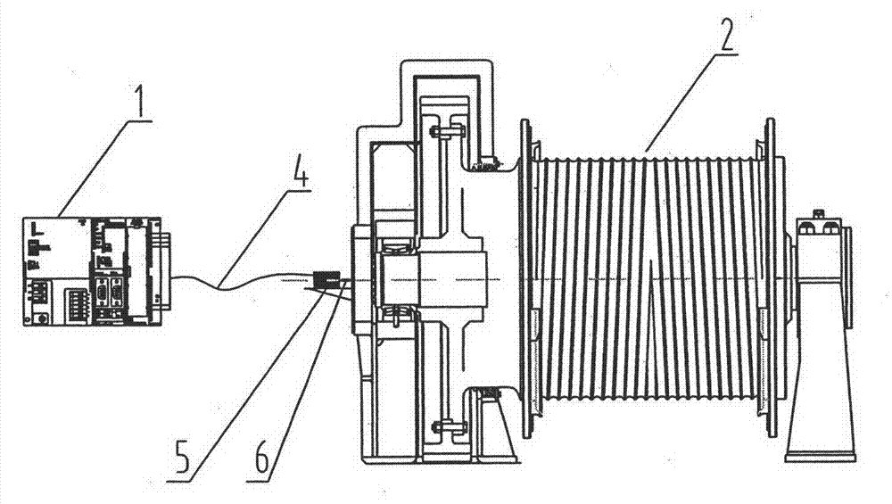
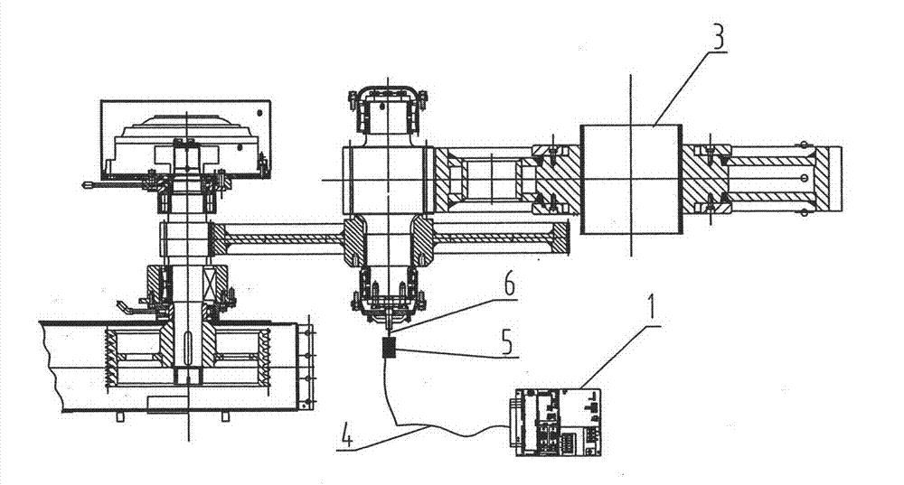
[0019] Such as figure 1 with figure 2 As shown, the installation diagram of lifting and pushing absolute encoder. The limit device of the lifting and pushing mechanism of the mining excavator, including the programmable controller PLC 1, the human-machine interface HMI, the lifting and pushing absolute value encoder; the lifting absolute value encoder 5 passes through the flexible shaft 6 is connected to the reel 2 of the lifting mechanism; the pushing absolute value encoder 5 is connected to the shaft of the reducer 3 of the pushing mechanism through the flexible shaft 6; the signal of the lifting and pushing absolute value encoder 5 Connect to the position input module of the programmable controller PLC through the shielded cable 4.

[0020] The limit method of the lifting and pushing mechanism of the mining excavator uses the programmable controller PLC 1, the man-machine interface...


PUM


Abstract

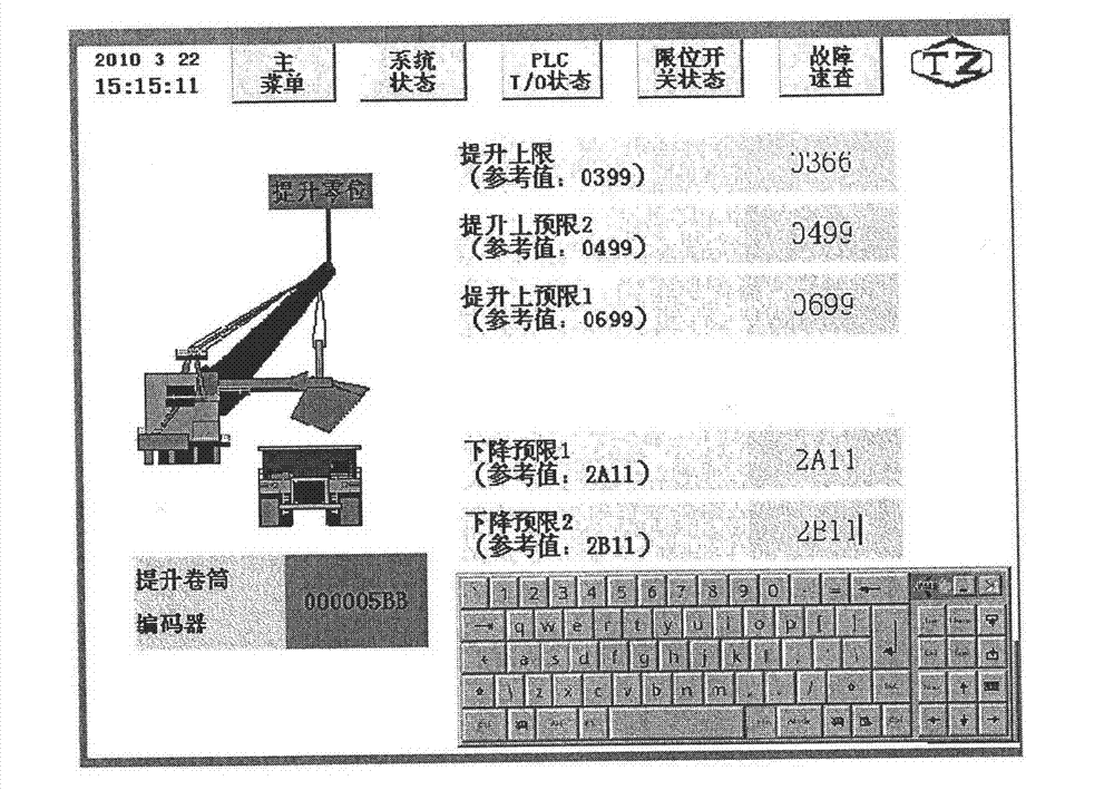
The invention discloses a limiting device of a lifting and pushing mechanism of a mine excavator, which comprises a programmable controller, a human-machine interface, a lifting absolute value coder and a pushing absolute value coder. The limiting device is characterized in that the lifting absolute value coder is connected with a lifting mechanism coiling block through a flexible shaft; the pushing absolute value coder is connected with a shaft of a pushing speed reducer through a flexible shaft; signals of the absolute value coders are connected to a position detection module of the programmable controller through a shielding cable; a central processing unit of the programmable controller reads the signals of the coders in real time through the position detection module; signal values of the signals are compared with a numerical value set by a touch screen to obtain numerical values of different limit points; and the given numerical values of a frequency converter are controlled by using the numerical values of the different limit points so that a lifting and pushing motor is controlled and lifting and pushing limit and pre-limit are controlled. According to the limiting device,the limit is accurate, a mechanical mechanism is protected, operation and control properties are improved, and urgent needs of a large excavator are met.

Description

Technical field [0001] The invention belongs to an electrical control system of a mining excavator, and relates to a limit device of a lifting and pushing mechanism of a mining excavator. Background technique [0002] At present, mining excavators are mainly used in open pit mining. The excavators vibrate greatly when they work. The lifting and pushing mechanisms of the domestic used excavators WK-4 and WK-10 are not equipped with electrical limit devices. The lifting mechanism of excavator is infinite, and there are often phenomena such as collision with the crown wheel or excessive lifting and dropping of the lifting rope. The pushing mechanism also has only mechanical baffles, which have a greater impact on the equipment, and frequent impacts will cause push The final shaft is broken, affecting the life of the equipment and mechanism. In addition, in order to meet the digging process requirements of large excavators, it is necessary to set multiple pre-limits. The use of coll...

Claims


Application Information

Patent Timeline
Patent Type & Authority Patents(China)
IPC IPC(8): E02F9/20
Inventor 苗根蝉刘晓星
Owner TAIYUAN HEAVY IND
Learn More