A device for separating projectile and projectile support

A separation device, projectile support technology, applied in the direction of projectiles, offensive equipment, weapon types, etc., can solve the problems of low connection strength, debris hitting the target board, and the interceptor can only be used one time, to achieve the connection High strength and impact reduction effect

Inactive Publication Date: 2011-12-28
XIAN MODERN CHEM RES INST
View PDF3 Cites 26 Cited by
  • Summary
  • Abstract
  • Description
  • Claims
  • Application Information

AI Technical Summary

Problems solved by technology

However, the cone-shaped interceptor cannot intercept the part of the shell that is cut off from the back of the projectile; the deformation and collapse of the cone during the impact process will also cause a part of the debris to hit the target plate
Secondly, after the projectile and the bullet rest are separated, the entire interceptor will be separated from the muzzle and fly forward. A large mass blocking plate must be placed in front of it, making the overall structure complex, and the tapered mouth interceptor is not compatible with the muzzle and the interceptor. The components of the interceptor are all bonded and connected with 502 glue, the connection strength is low, and the entire interceptor can only be used once
Finally, it has not been reported whether the projectile with heavier weight and larger geometric size can be successfully separated

Method used


Image

  • A device for separating projectile and projectile support
  • A device for separating projectile and projectile support
  • A device for separating projectile and projectile support

Examples


Embodiment Construction

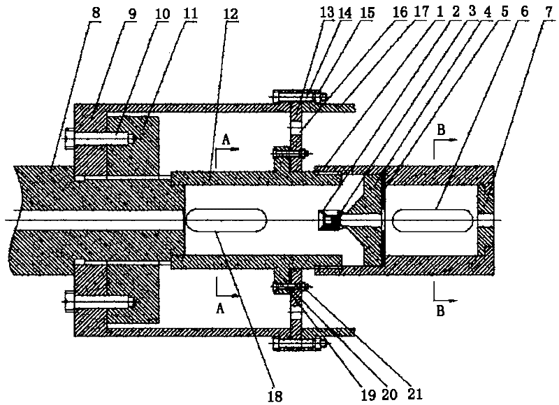
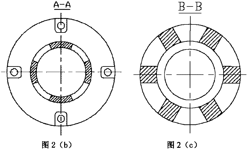
[0017] Referring to Fig. 2, Fig. 2 is the structure schematic diagram of the moment of separation of the projectile and cartridge separating device of the present invention, the shunt chamber 9 of the light gas gun body is arranged on the gun barrel 8, and the shunt chamber 9 of the light gas gun body is connected with a flange by a screw 10 Disc 11 is provided with guide chamber 12 and separation chamber 1 at the outlet of gun barrel 8. The guide chamber 12 is provided with an elliptical air release port 18, the separation chamber 1 is provided with an oval air release port 6, and the guide chamber 12 is connected with a support plate. 13. The support plate 13 is connected with the split chamber 9 of the light gas gun body and the test chamber 17 of the light gas gun body by screws, and the support plate 13 has a gas leak port 16 .

[0018] One end of the separation chamber 1 is threadedly connected to the guide chamber 12 , and a separation block 4 , a buffer plate 5 and a bl...


PUM


Abstract

The invention discloses a device for separating a bullet and a bullet support, which comprises a guide chamber and a separating chamber which are arranged on the outlet of a gun barrel. The guide chamber and the separating chamber are respectively provided with an elliptical air release hole; the guide chamber is connected with support plates; a separating block, a buffering plate and a stopping block are arranged in the cavity of the separating chamber; one end of the separating block is conical; the mouth of the separating block is in a horn shape; the other end of the separating block is cylindrical, and a variable-diameter centre hole penetrates through the cylindrical end of the separating block; the cylindrical end of the separating block is positioned by a boss in the separating chamber; the buffering plate is arranged between the cylindrical end of the separating block and the boss in the separating chamber; the mounting position of the conical end of the separating block faces to the gun barrel; the stopping block is of a stepped cylindrical structure with a centre hole; the stopping block is located at the bottom part of the separating chamber and is positioned by the boss in the separating chamber; and the centre hole of the separating block and the centre hole of the stopping block are coaxially arranged. The device for separating the bullet and the bullet support is capable of effectively preventing fragments generated in the impact process from impacting a target plate together with a bullet.

Description

technical field [0001] The invention relates to a separating device, in particular to a projectile carrier separating device used for an ultra-high-speed projectile launching device. Background technique [0002] The research on the ultra-high-speed impact process is of great significance to scientific and technological fields such as astrophysics, geophysics, artificial satellite protection, and tactical weapon interception. The two-stage light gas gun has become one of the main means of launching ultra-high-speed projectiles because of its wide adaptability to the shape, quality, material and speed of projectiles. In the test, in order to prevent the high-speed motion of the metal projectile in the launch tube from causing serious damage to the launch tube, it is necessary to use plastic to make the bullet holder, which contains the projectile to be launched. When launching, the plastic bullet holder directly contacts and rubs against the launch tube. After exiting the mu...

Claims


Application Information

Patent Timeline
Patent Type & Authority Applications(China)
IPC IPC(8): F42B10/00
Inventor 苏健军屈可朋孔军利肖玮王胜强董树南李亮亮沈飞韩天一闫潇敏
Owner XIAN MODERN CHEM RES INST
Why Eureka
Try Eureka