
Stator-rotor structure with replaceable crushing gear rings for high shearing equipment

A high-shear, stator-rotor technology, applied in the manufacture of the stator/rotor body, etc., can solve the problems such as the number of teeth and the gap between the rack and rack cannot be adjusted, the flow of energy materials is not smooth, the size of the stator and rotor is large, and the crushing effect is improved. , low cost of use, and optimized material flow state

Active Publication Date: 2013-01-02
无锡轻大食品装备有限公司
View PDF2 Cites 0 Cited by
  • Summary
  • Abstract
  • Description
  • Claims
  • Application Information

AI Technical Summary

Problems solved by technology

In the prior art, the stator and rotor of the high-shear equipment are processed by integral wire cutting or milling, and the number of teeth of each ring gear and the opening clearance of the rack are the same, which results in a larger diameter The material utilization rate of the large outer ring gear is very low, and it is impossible to form the crushing effect that the inner ring is coarsely crushed first, and then the outer ring is finely crushed; in addition, the stator and rotor are vulnerable parts, once a certain rack or ring gear If it is worn out, the entire stator or rotor needs to be replaced, which leads to a waste of maintenance costs; moreover, for the integral stator and rotor, the number of teeth of the ring gear and the clearance of the rack cannot be adjusted. In order to achieve different To achieve the best crushing effect and adapt to different crushing requirements, different stators and rotors need to be replaced, and the cost of use is also high
[0003] In addition, a stator-rotor structure is also described in a patent document titled "A Stator-Rotor Structure of a Detachable High-shear Grinding Equipment" filed by the inventor earlier, and the publication number is "CN101873015A". The crushing rack is installed as a single piece, but this type of installation makes the size of the stator and rotor larger, which brings more energy consumption, and the ratio of tooth thickness to inter-tooth gap (length-to-diameter ratio) is relatively large. The problem of poor material flow caused by

Method used


Image

  • Stator-rotor structure with replaceable crushing gear rings for high shearing equipment
  • Stator-rotor structure with replaceable crushing gear rings for high shearing equipment
  • Stator-rotor structure with replaceable crushing gear rings for high shearing equipment

Examples


Embodiment Construction

[0023] The present invention will be further described below in conjunction with the embodiments in the accompanying drawings.

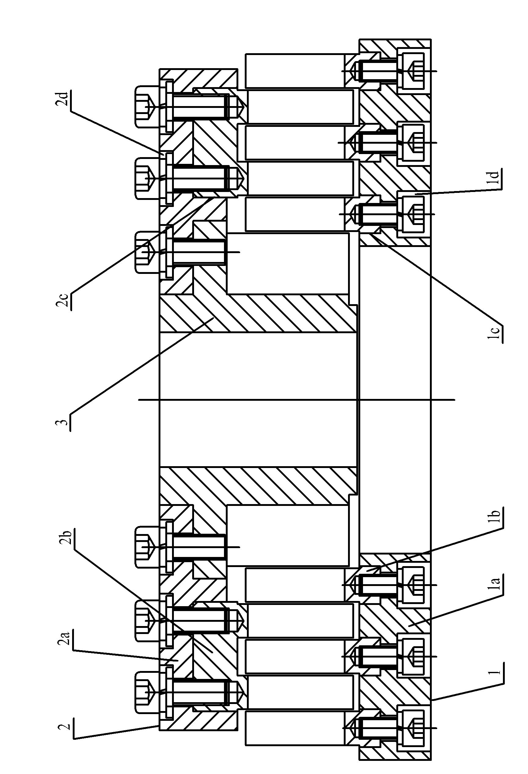
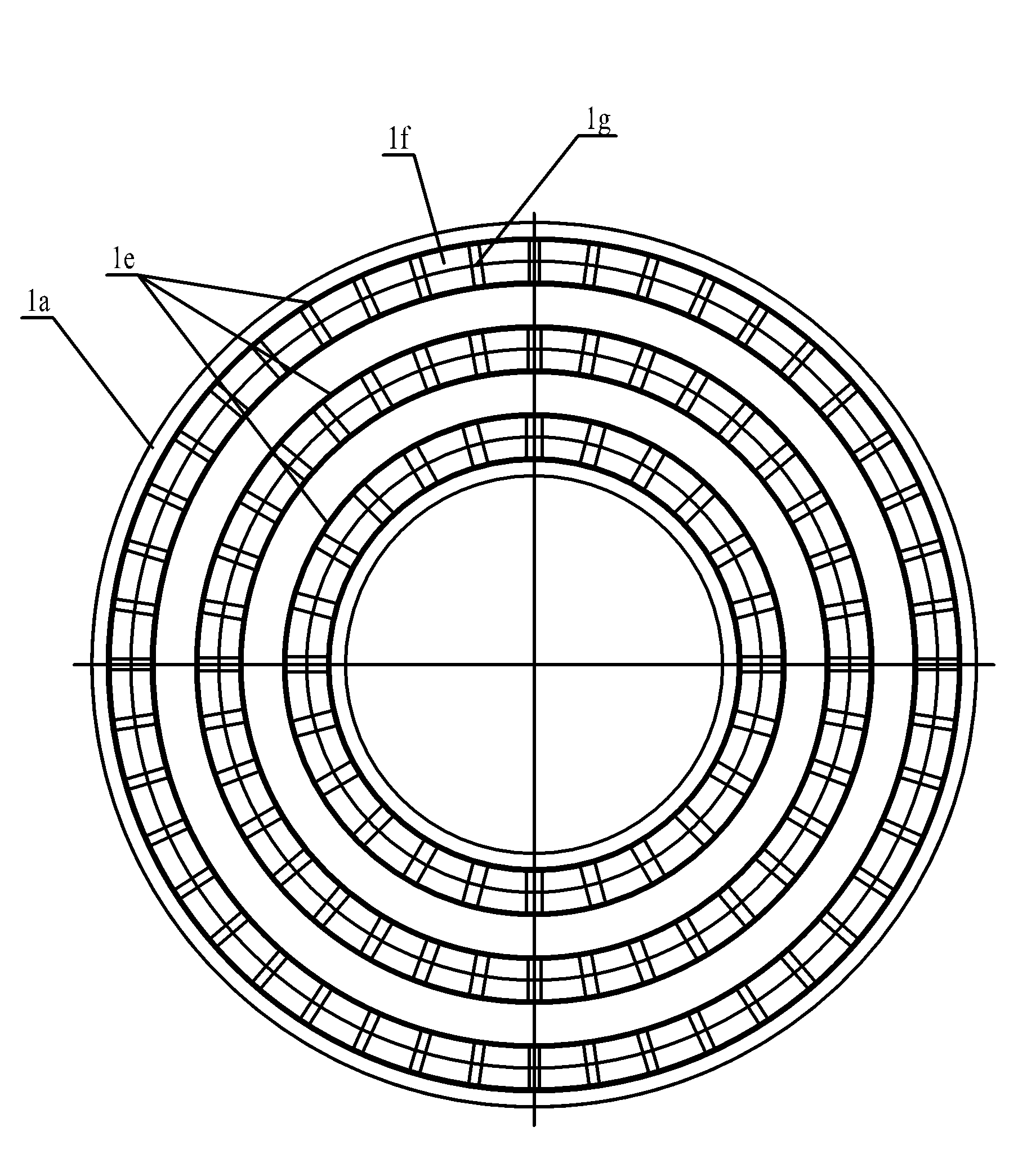
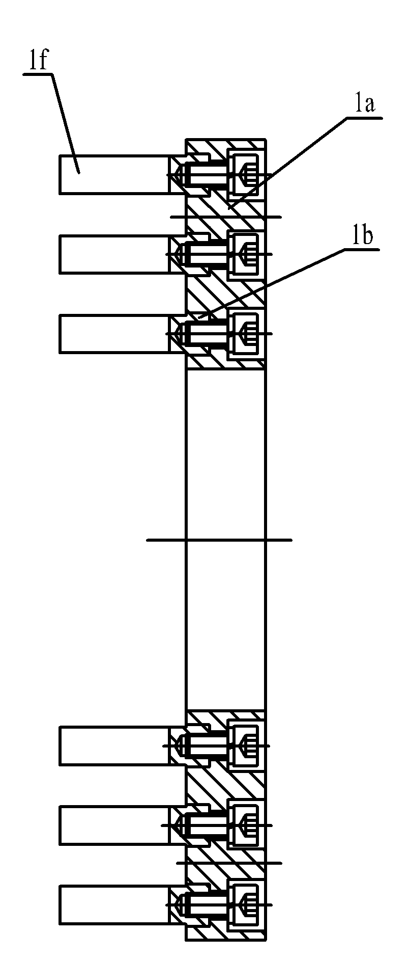
[0024] As shown in the figure, the replaceable stator-rotor structure of the crushing ring gear in the embodiment mainly includes two parts: a stator 1 and a rotor 2 . The stator 1 is mainly composed of a stator base 1a and a stator crushing ring gear 1b. The stator base 1a is provided with three concentric annular stator positioning grooves 1c, and a detachable stator crushing groove 1c is embedded in each annular stator positioning groove 1c. Ring gear 1b; the bottom of each annular stator positioning groove 1c is provided with mounting holes 1d uniformly distributed along its circumference, and the stator crushing ring gear 1b is fixed on the stator base 1a by fastening screws passing through the mounting holes 1d; in the embodiment The stator crushing ring gear 1b is provided with a layer of stator crushing gear ring 1e, and the stator crushing g...


PUM


Abstract

The invention relates to a stator-rotor structure with replaceable crushing gear rings applied to high shearing equipment. The structure provided by the invention comprises a stator and a rotor, and is characterized in that a stator base is provided with at least one concentric annular stator locating slot, and a stator crushing gear ring is embedded in the annular stator locating slot; a rotor base is provided with at least one concentric annular rotor locating slot, and a rotor crushing gear ring is embedded in the annular rotor locating slot; the stator crushing gear ring is provided with at least one layer of stator crushing toothed ring, and stator crushing racks are uniformly distributed along the circumferential direction of the stator crushing toothed ring; the rotor crushing gearring is provided with at least one layer of rotor crushing toothed ring, and rotor crushing racks are uniformly distributed along the circumferential direction of the rotor crushing toothed ring; andthe stator crushing toothed ring and the rotor crushing toothed ring are arranged in a staggered manner along the radial direction . The stator-rotor structure provided by the invention is simple in structure, convenient to disassemble, lower in energy consumption and more optimal in material flowing state, and can be used for enlarging the application range of the high shearing equipment and lowering the use cost of the equipment.

Description

technical field [0001] The invention belongs to the technical field of high-shear crushing and homogenizing equipment, and relates to a stator-rotor structure of high-shear equipment, in particular to a stator-rotor structure with a replaceable crushing ring gear. Background technique [0002] In the food and pharmaceutical industry and petrochemical industry, high-shear equipment is a new type of equipment used for crushing, homogenization, emulsification, dispersion and mixing. Its main principle is to use the relative shearing effect between the crushing rack on the stator and the rotor to reduce the size of the larger particle material, or / and realize the uniform mixing of different phase materials. In the prior art, the stator and rotor of the high-shear equipment are processed by integral wire cutting or milling, and the number of teeth of each ring gear and the opening clearance of the rack are the same, which results in a larger diameter The material utilization rat...

Claims


Application Information

Patent Timeline
Patent Type & Authority Patents(China)
IPC IPC(8): H02K15/02
Inventor 张裕中高青令张茂龙李辉赵欢陈乐磊
Owner 无锡轻大食品装备有限公司
Learn More