
Inductive circuit arrangement

A technology of inductive circuit and capacitive circuit, which is applied in the direction of circuits, parts of amplification devices, electrical components, etc.

Active Publication Date: 2014-04-30
AMPLEON NETHERLANDS
View PDF7 Cites 2 Cited by
  • Summary
  • Abstract
  • Description
  • Claims
  • Application Information

AI Technical Summary

Problems solved by technology

[0018] In conjunction with various example embodiments, an input circuit provides power to main and peaking amplifiers to address challenges for a variety of applications and devices such as those discussed above

Method used


Image

  • Inductive circuit arrangement
  • Inductive circuit arrangement
  • Inductive circuit arrangement

Examples


Embodiment Construction

[0033] While the invention includes various modifications and alternative forms, these are shown by way of example in the drawings and details thereof will be described in detail. It should be understood, however, that the invention is not limited to the particular embodiments described herein. On the contrary, the invention covers all modifications, equivalents, and alternatives falling within the scope including various aspects as defined in the claims.

[0034] The invention is applicable to many different types of processes, devices and arrangements for use with various circuits, including inductive circuits for amplifiers, and various types of circuits such as circuits including wireless communications and radio frequency (RF) / microwave signals. application. While the invention is not necessarily so limited, various aspects of the invention can be understood through the discussion of examples using the context.

[0035] In connection with various example embodiments, a ...


PUM


Abstract

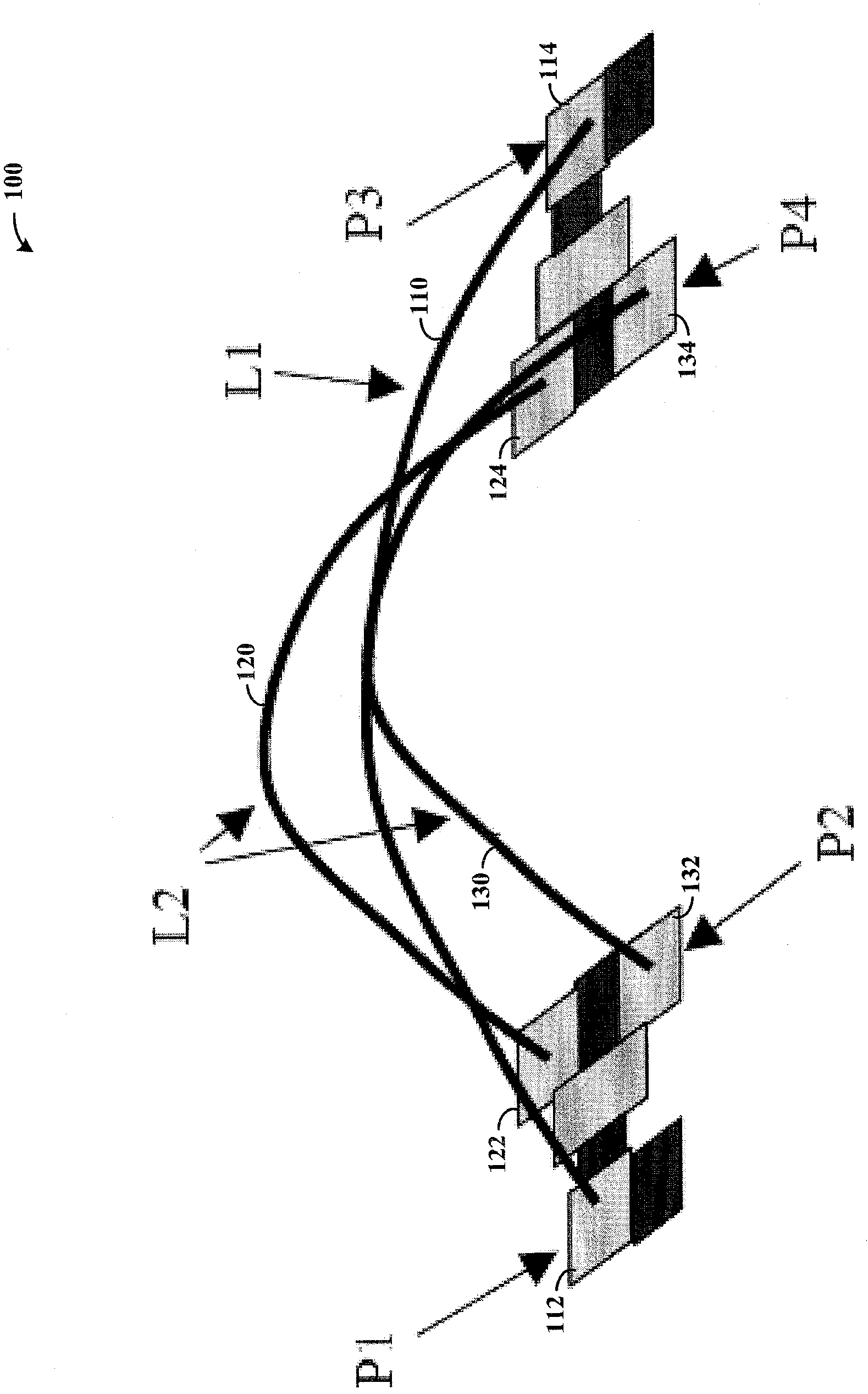
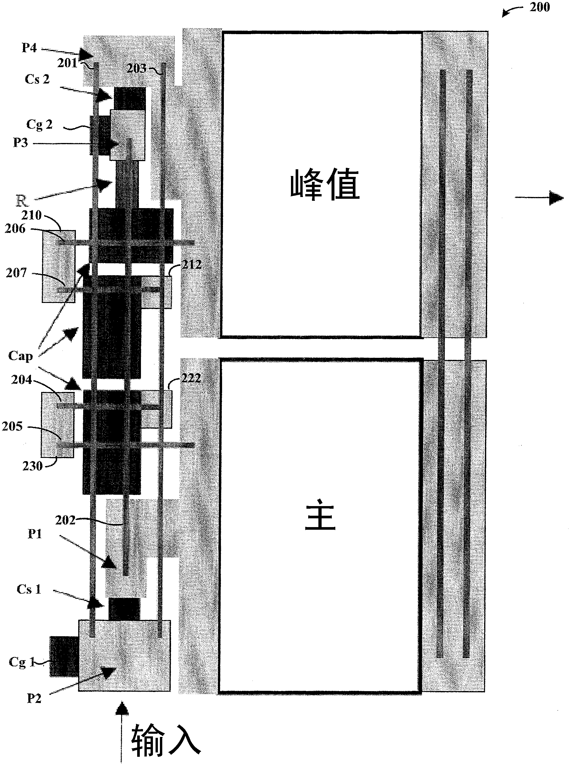
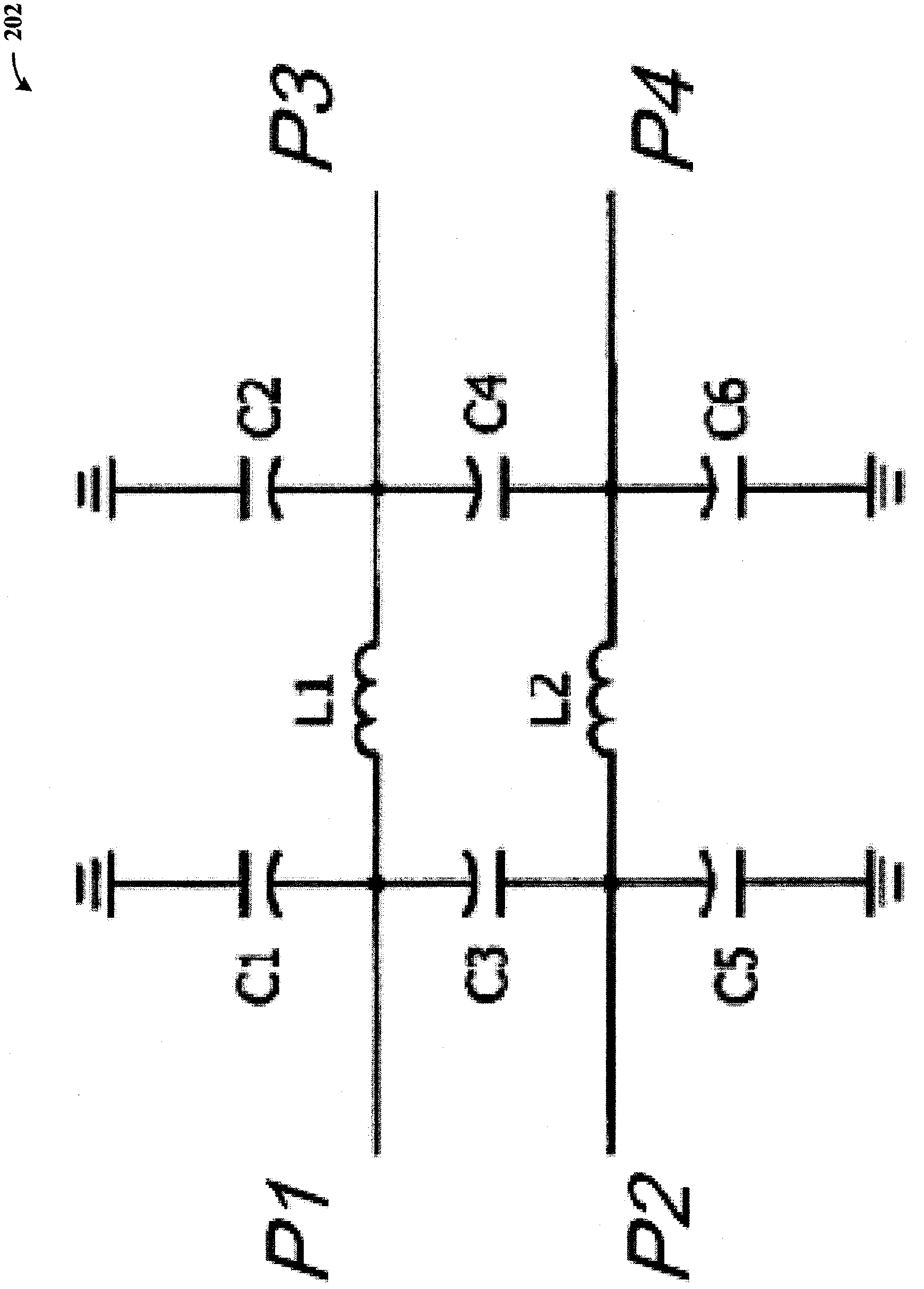
A bond wire circuit (100) includes at least three bond wires (110,120,130) arranged to split an input signal into two output signals. In connection with various example embodiments, bond wires (110,120,130) are arranged in a generally parallel manner to mitigate magnetic coupling and related issues for splitting an input signal and providing each of split signals to an amplifier. The bond wires (110,120,130) are connected by capacitive circuits that facilitate the splitting, and in some applications, additional capacitive (to ground / reference) and load circuits to further facilitate the splitting of the input signals for specific amplifier circuit implementations, and applications to various loads. In some implementations, the input signals are split in equal or arbitrary portions with frequency independent phase differences in a wide frequency band, with isolation between ports of the circuit.

Description

technical field [0001] The invention relates to the field of circuits, in particular to an inductance circuit device. Background technique [0002] Various input circuits suffer from undesirable characteristics, particularly with respect to compact size and efficiency, and with respect to particular applications requiring or benefiting from input isolation. These input circuits can be used to provide inputs to various components such as amplifiers used in radio frequency circuits. [0003] Amplifiers for a variety of applications have increased dramatically, including high power MMIC amplifiers such as those used in mobile communication base stations. For these amplifiers, high power efficiency and small size are required, however these aspects are difficult to achieve. In general, higher power amplifiers are larger, and reducing component size can limit power capabilities. Furthermore, the high power devices used in these amplifiers typically must exhibit very high power...

Claims


Application Information

Patent Timeline
Patent Type & Authority Patents(China)
IPC IPC(8): H03F1/42
CPCH01L2223/6644H01L2924/01055H01L2223/6655H01L2924/01082H03F1/0288H01L2924/3011H01L24/48H01L2223/6611H01L2924/01033H01L2924/01005H01L2924/01019H01L2924/01006H01L23/66H01L2924/01074H01L2924/01014H01L2924/19041H03F3/195H01L2224/48091H01L2924/30107H01L2924/3025H01L2924/1423H01L24/49H01L2224/49H01L2924/1306H01L2924/1305H01L2924/00014H01L2924/14H01L2924/00H01L2224/45099
Inventor 伊戈尔·布莱德诺夫
Owner AMPLEON NETHERLANDS
Learn More