
Main bus-bar, branch bus-bar, transfer connector and bus-bar assembly

A technology of branch busbar and main busbar, applied in busbar installation, cooling busbar device, open busbar installation, etc., to achieve the best dynamic stability, good space electric field, and best mechanical bending strength

Active Publication Date: 2016-04-13
ABB (SCHWEIZ) AG
View PDF10 Cites 3 Cited by
  • Summary
  • Abstract
  • Description
  • Claims
  • Application Information

AI Technical Summary

Problems solved by technology

However, due to the structure of the branch bus, the branch bus is only suitable for bonding to the planar main bus

Method used


Image

  • Main bus-bar, branch bus-bar, transfer connector and bus-bar assembly
  • Main bus-bar, branch bus-bar, transfer connector and bus-bar assembly
  • Main bus-bar, branch bus-bar, transfer connector and bus-bar assembly

Examples


Embodiment Construction

[0054] Hereinafter, embodiments of the present disclosure will be described more specifically with reference to the above drawings. It should be understood that these embodiments are presented only to enable those skilled in the art to better understand and implement the present disclosure, and are not intended to limit the scope of the present disclosure in any way.

[0055] Generally, all terms used in the claims are to be interpreted according to their ordinary meaning in the technical field, unless explicitly defined otherwise herein. References to "a / the / said [element, device, part, means, step, etc.]" are to be construed openly as referring to at least one instance of said element, device, part, means, step, etc., rather than A plurality of such devices, components, means, units, steps etc. is excluded unless expressly defined otherwise. Furthermore, the indefinite article "a" as used herein does not exclude a plurality of such steps, units, modules, devices and objects...


PUM


Abstract

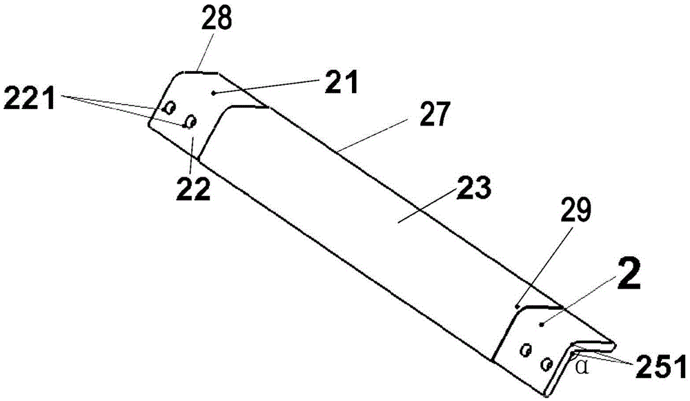
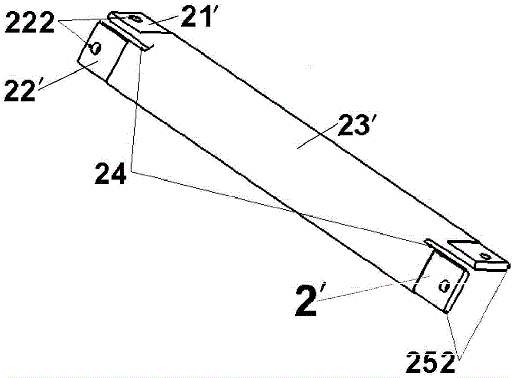
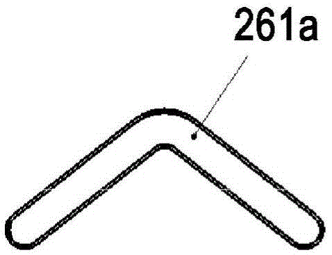
A main bus-bar consists of a first elongated flat portion and a second elongated flat portion. A longitudinal side of the first elongated flat portion and a longitudinal side of the second elongated flat portion are arranged to be joined with each other at a predetermined angle. The thickness of each of the first elongated flat portion and the second elongated flat portion is non-uniform. Hence the skin effect and proximity effect caused by current carried in the main bus-bar can be reduced greatly. The main bus-bar can be connected to a branch bus-bar directly or be connected to a branch bus-bar by a transfer connector in a bus-bar assembly or a bus-bar system.

Description

technical field [0001] Embodiments of the present disclosure relate generally to the field of power products, and more particularly to main busbars, branch busbars, transition blocks, and busbar assemblies Background technique [0002] Currently, busbars are widely used to transfer power from outside the power source to various electrical components in distribution cabinets or switchgear. Most of the cross-sectional shapes of existing main busbars are hollow rectangles or circles. . [0003] Rectangular busbars have a simple shape and are easy to manufacture, but have poor mechanical bending strength. The amount of current carried by the rectangular bus bars is also relatively small due to the "skin effect" and "proximity effect" of the current flow. In addition, the outer heat dissipation surface of the rectangular bus bar is small, which is not conducive to heat radiation. When it is used as a large current bus, relatively more material and more space are required. Fu...

Claims


Application Information

Patent Timeline
Patent Type & Authority Applications(China)
IPC IPC(8): H02G5/02
CPCH02G5/00H02G5/10H01B5/02
Inventor 杨长洲张洋黄立群王德龙刘晓东颜聪明王哲张欣
Owner ABB (SCHWEIZ) AG
Learn More