Electric wire

a technology of electric wire and wire, applied in the direction of insulated conductors, cables, conductors, etc., to achieve the effect of enhancing the transmission of current in high frequency

Inactive Publication Date: 2005-11-22
GOTO DENISH CO LTD
View PDF9 Cites 23 Cited by
  • Summary
  • Abstract
  • Description
  • Claims
  • Application Information

AI Technical Summary

Benefits of technology

[0029]Therefore, a surface area of the conductive portion of the electric wire is increased so that the skin effect being caused by high frequency current is increased and then the current transmissibility in high frequency is enhanced. Furthermore, the electric wire is formed by combining wire elements integrally to engaged mutually the convexo-concave surfaces of wire elements, providing a convexo-concave surface on a surface of a conductive portion, to provide the predetermined amount of grooves or concave portions having predetermined section, extending in a direction of thickness or toward a center of the conductive portion, on the surface of the conductive portion along lengthwise the conductive portion so that current of the combined wire can flow not only in surface zone of the conductive portion but also in the center zone of the conductive portion and then the current transmissibility is enhanced.

Problems solved by technology

However, a square electric wire having a conductive portion A′ with a square section as shown in FIG. 14 or a flat electric wire having a conductive portion with a rectangular section as shown in FIG. 15 does not have enough current flow in a surface zone B by the skin effect.

Method used


Image

  • Electric wire
  • Electric wire
  • Electric wire

Examples


first embodiment

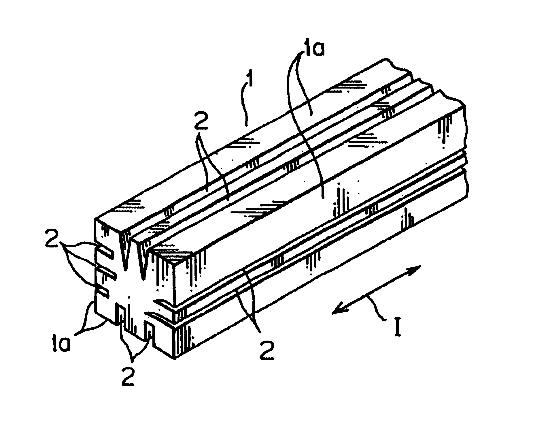
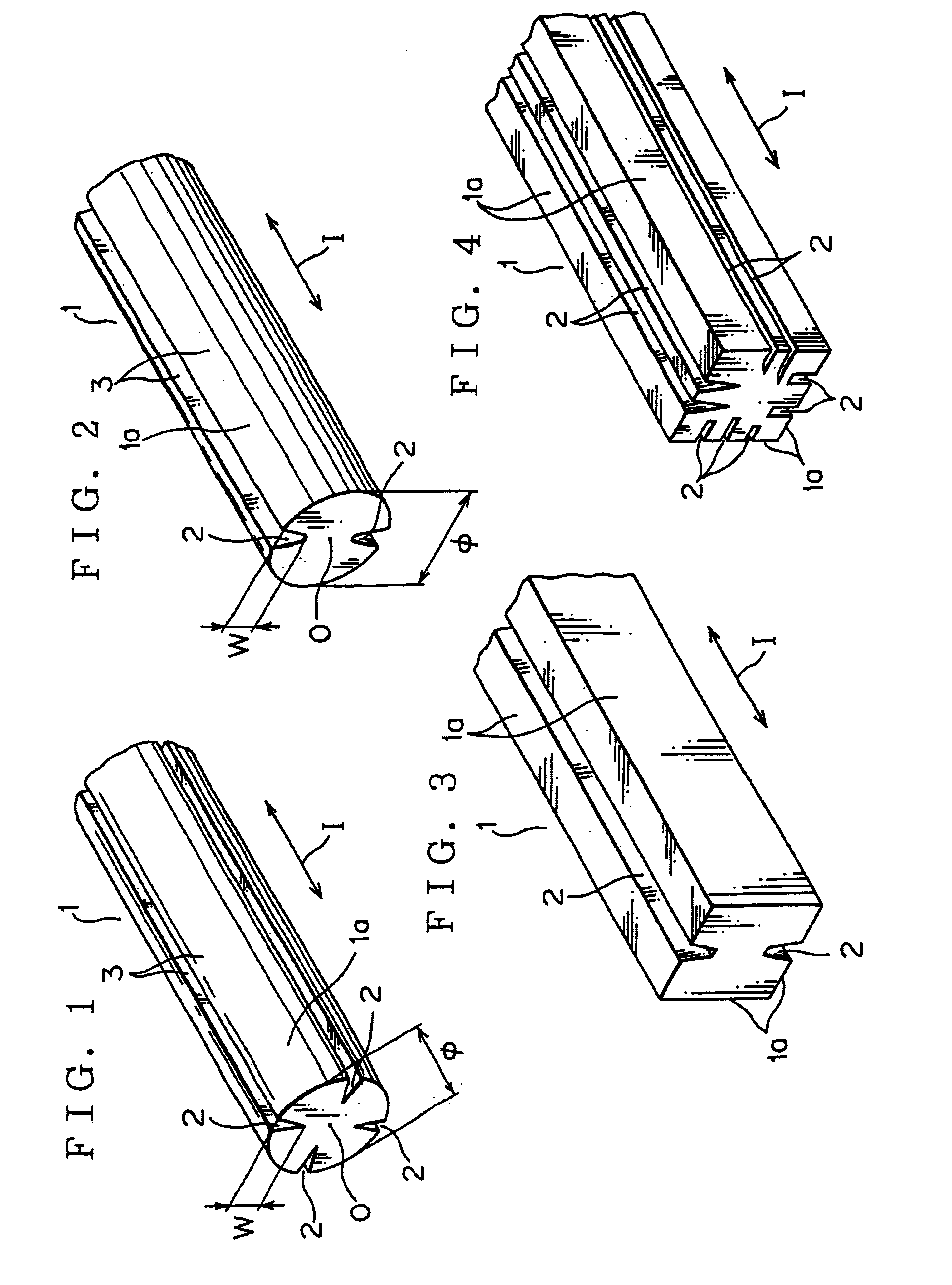
[0051]FIG. 1 shows the groove 2 to have a cross section formed into V-shape on the surface 1a of the conductive portion 1. Not limited to above, the groove 2 may be formed with a cross section of U-shape in the other electric wire according to this invention shown in FIG. 2 or with a cross section of trapezoid shape, not shown.

[0052]When the conductive portion is made of metal such as copper, aluminum, iron or alloy of them, draw forming with a draw die or press forming with a press roller to form a required size of an electric wire is well known so that a groove 2 with a predetermined depth W on a surface 1a of a conductive portion 1 may be formed simultaneously. As the other forming method, a groove 2 can be formed by an electrical method with laser, maser, arc or plasma, or by grinding with a diamond fine tool and NC machine.

[0053]When the conductive portion 1 is formed with electrical conductive plastic or non-metal by injection molding or extrusion molding, a groove 2 may be fo...

second embodiment

[0059]FIG. 3 shows an electric wire according to this invention.

[0060]According to the embodiment, instead of the first embodiment which conductive portion 1 has the round outline of the cross section shown in FIGS. 1 and 2, the conductive portion 1 has outline of a cross section being formed into square so that the space factor is improved and the resistance is reduced and then the current intensity flowing in the conductive portion 1 is increased by the skin effect. The structure and action of the second embodiment is similar as that of the first embodiment other than forming the cross section of the groove 2 with a predetermined depth W, extending in a direction of thickness from the surface 1a of the conductive portion 1, into trapezoid.

[0061]FIG. 4 shows the other electric wire according to the second embodiment of this invention. The conductive portion 1 is formed on cross section into square similarly as the electric wire shown in FIG. 3.

[0062]In the other electric wire, prov...

third embodiment

[0063]FIG. 5 shows an electric wire according to this invention.

[0064]Forming a conductive portion 1 with an electric conductive material and providing predetermined amount of voids 2′ in vicinity of the surface 1a of the conductive portion 1 along the longer direction I thereof, the surface area of the conductive portion 1 is increased larger than a surface area of a round electric wire by prior art with round section shown in FIG. 12 and the skin effect is increased and the space factor of the conductive portion 1 is increased. Therefore, current intensity flowing in the surface 1a of the conductive portion 1 is increased. The current transmissibility is enhanced remarkably when the frequency of the current flowing in the conductive portion 1 is increased.


PUM

PropertyMeasurementUnit
diameteraaaaaaaaaa
current intensityaaaaaaaaaa
currentaaaaaaaaaa

Abstract

An electric wire having a conductive portion with grooves on the surface thereof to increase a surface area of the conductive portion for enlarging the skin effect in high frequency current and enhancing the transmissibility and the space factor in high frequency current is provided. The conductive portion 1a being made of an electric conductive material is formed on the surface 1a with a convexo-concave surface 3 to provide predetermined amount of grooves 2 or concave portions 20 having a predetermined section with a predetermined depth W extending in a direction of thickness or toward a center of the conductive portion on the surface of the conductive portion along lengthwise the conductive portion

Description

RELATED APPLICATION[0001]This application is a divisional of U.S. Ser. No. 10 / 214,069 filed on Aug. 7, 2002 now abandoned.BACKGROUND OF THE INVENTION[0002]1. Field of the Invention[0003]This invention relates to an electric wire, which is enhanced on transmissibility of high-frequency current, especially to enlarge conductor skin effect in high-frequency current flow.[0004]2. Description of the Related Art[0005]When an alternating current flows as current I in an electrical conductive portion A, such as a metal, having uniform electrical conductivity σ and a frequency of the current is increased, the current does not flow in the center zone O of the electrical conductive portion A and the current flows concentratively in a surface zone B. The phenomenon is know as the conductor skin effect or the skin effect.[0006]This phenomenon is caused by that an eddy current Ie to restrain a time response of a magnetic flux change by a circular magnetic field being generated in the conductive p...

Claims


Application Information

Patent Timeline
Patent Type & Authority Patents(United States)
IPC IPC(8): H01B7/30H01B7/00H01B5/02
CPCH01B7/0009H01B7/30
Inventor GOTO, YOSHIHIDE
Owner GOTO DENISH CO LTD
Why Eureka
Try Eureka