Heating apparatus and induction heating control method
a technology of induction heating and heating apparatus, which is applied in the direction of electrographic process apparatus, ohmic resistance heating, instruments, etc., can solve the problems of enlarged whole device, increased cost, and increased cost as compared
- Summary
- Abstract
- Description
- Claims
- Application Information
AI Technical Summary
Benefits of technology
Problems solved by technology
Method used
Image
Examples
first embodiment
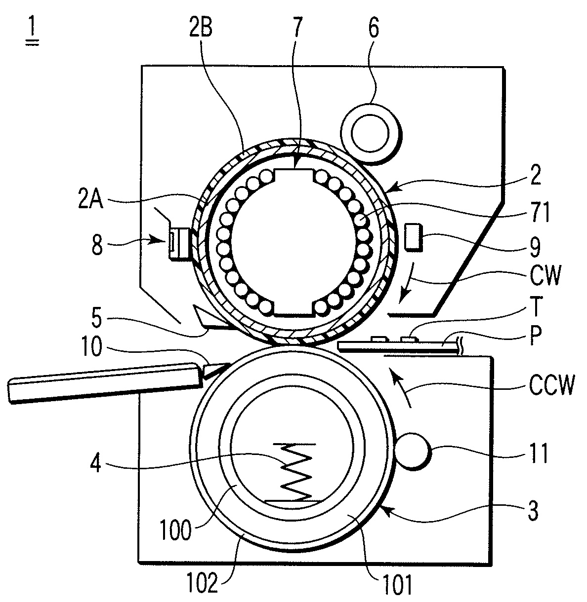
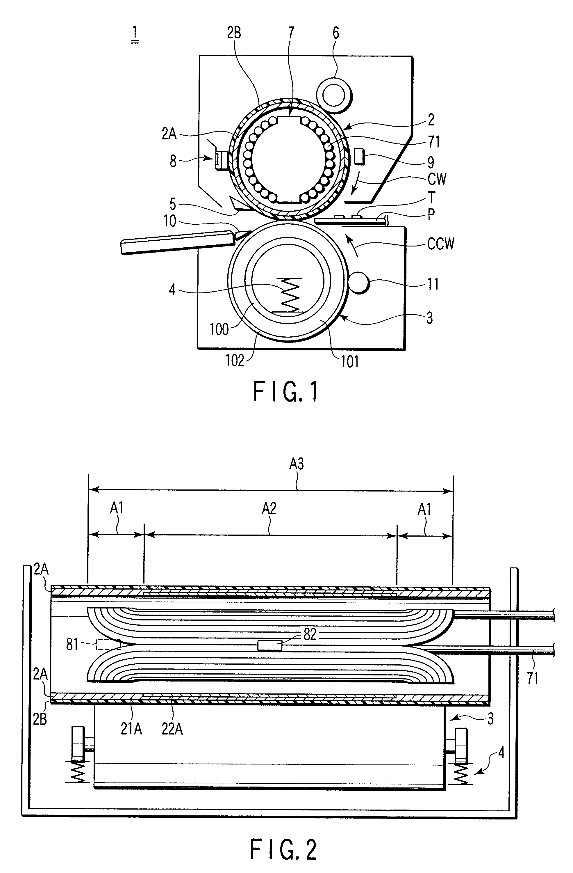
[0049]FIG. 1 shows one example of a fixing device to which an embodiment of this invention is applied. FIG. 2 is a schematic diagram of the fixing device shown in FIG. 1 as viewed from a different direction.
[0050]As shown in FIG. 1, a fixing device 1 has a heating member (heating roller) 2, a pressurizing member (pressurizing roller) 3, a pressurizing spring 4, a peeling claw 5, a cleaning roller 6, an induction heating unit 7, a temperature detecting section 8, and a thermostat 9.
[0051]The heating roller 2 includes a rolled conductive layer 2A constituted by forming a conductive material into a cylindrical shape, and a coating layer (mold-releasing layer) 2B disposed on an outer peripheral surface of this conductive layer 2A and made of a fluorine resin such as an ethylene tetrafluoride resin. This heating roller 2 has a 20 μm thick mold-releasing layer formed on the surface of the conductive layer 2A having a diameter of 40 mm and a thickness of 1 mm.
[0052]The pressurizing roller ...
second embodiment
[0102]Next, there will be another example of the first embodiment with reference to FIGS. 5 and 6. FIG. 5 shows an example of a fixing device to which the present embodiment is applicable. FIG. 6 shows a schematic diagram of the fixing device shown in FIG. 5 as viewed from a different direction. It is to be noted that components having the same constitutions and functions as those of components shown in FIGS. 1 to 4 are denoted with the same reference numerals, and detailed description thereof is omitted.
[0103]As shown in FIG. 5, a fixing device 100 has a heating roller 200, an induction heating unit 700, a pressurizing roller 3, a pressurizing spring 4, a peeling claw 5, a cleaning roller 6, a temperature detecting section 8, and a thermostat 9.
[0104]The heating roller 200 has: a shaft 200a made of a material having a rigidity (hardness) such that the material does not deform under a predetermined pressure; an elastic layer (a foam rubber layer, a sponge layer, and a silicon rubber...
third embodiment
[0111]Next, there will be described another example of a first embodiment with reference to FIGS. 7, 8A, and 8B. FIG. 7 shows an example of a fixing device to which the present embodiment is applicable. FIGS. 8A and 8B show schematic diagrams of a heating roller 220 which is applicable to the fixing device shown in FIG. 7.
[0112]As shown in FIG. 7, a fixing device 120 includes: a fixing belt 12; the heating roller 220; a pressurizing roller 321; a fixing roller 322; and an induction heating unit 720.
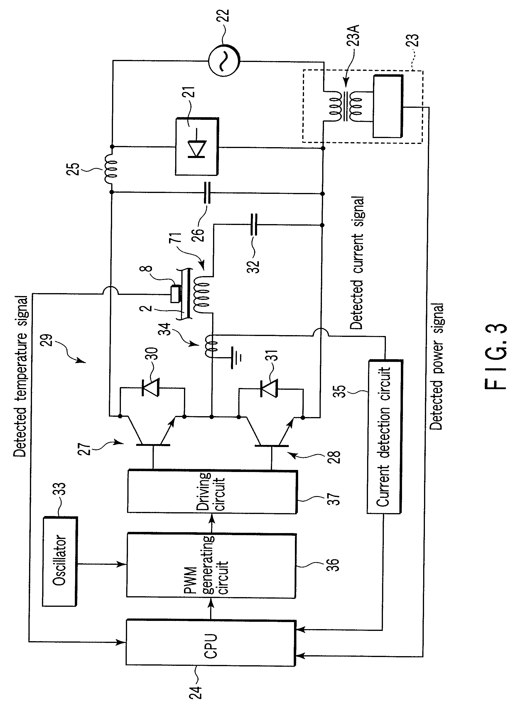
[0113]The induction heating unit 720 is disposed externally along the heating roller 220, and the fixing belt 12 is sandwiched between the induction heating unit and the heating roller 220. The induction heating unit is connected to an induction heating control circuit described above with reference to FIG. 3, and includes: an exciting coil 721 to which a predetermined power is supplied and which supplies a predetermined magnetic field to the heating roller 220; and a magnetic core 722.
[0...
PUM
 Abstract
Description
Claims
Application Information
 - R&D
- Intellectual Property
- Life Sciences
- Materials
- Tech Scout
- Unparalleled Data Quality
- Higher Quality Content
- 60% Fewer Hallucinations
Browse by: Latest US Patents, China's latest patents, Technical Efficacy Thesaurus, Application Domain, Technology Topic, Popular Technical Reports.
© 2025 PatSnap. All rights reserved.Legal|Privacy policy|Modern Slavery Act Transparency Statement|Sitemap|About US| Contact US: help@patsnap.com


