
Molten glass stirring device

A technology of molten glass and stirring device, which is applied in mixers with rotating stirring device, glass production, glass molding, etc., which can solve problems such as difficulty in obtaining molten glass homogeneity, and achieve high transparency and excellent homogeneity , Excellent effect of homogeneity

Inactive Publication Date: 2011-12-28
ASAHI GLASS CO LTD
View PDF9 Cites 6 Cited by
  • Summary
  • Abstract
  • Description
  • Claims
  • Application Information

AI Technical Summary

Problems solved by technology

[0013] In the case of requiring such extremely high homogeneity, it is difficult to obtain sufficient homogeneity of molten glass with existing stirring devices

Method used


Image

  • Molten glass stirring device
  • Molten glass stirring device
  • Molten glass stirring device

Examples


Embodiment 1

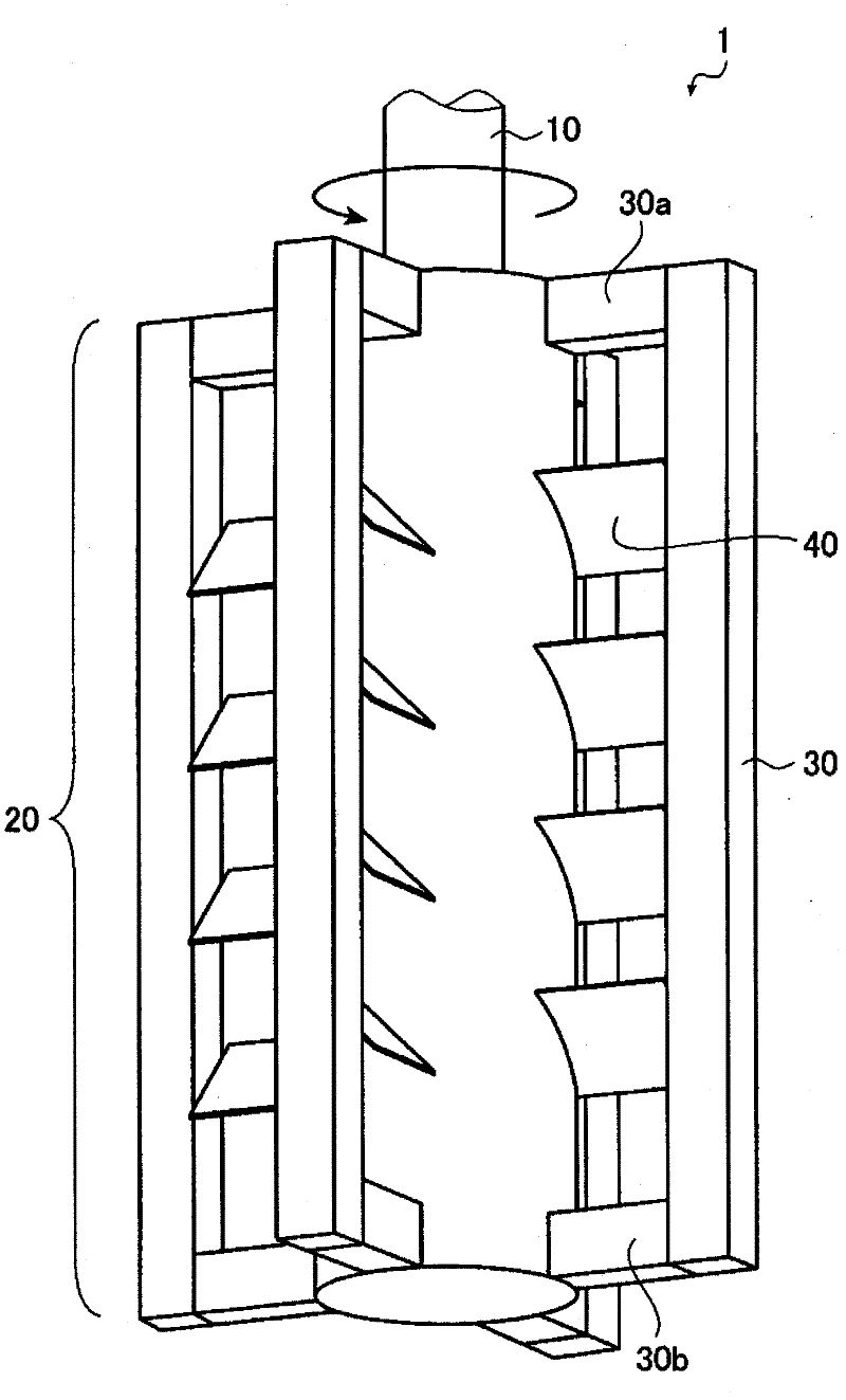
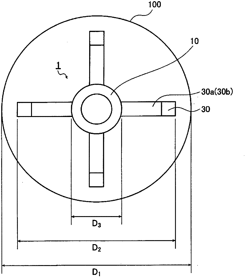
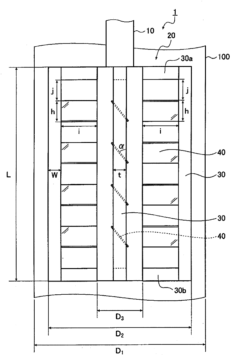
[0096] pair Figure 1~3 The flow of the fluid when the shown glass stirring device 1 of the present invention was inserted into the delivery pipe and stirred was evaluated. The dimensions of each part of the glass stirring device are as follows.

[0097] The maximum diameter D of the outer edge of the stirring part 20 2 : 38mm

[0098] The diameter of the central shaft 10 (the part that constitutes the stirring part 20) D 3 : 10mm

[0099] The length L of the longitudinal stirring blade 30: 60mm

[0100] Width W of longitudinal stirring blade 30: 3.8mm

[0101] Thickness t of longitudinal stirring blade 30: 3.8mm

[0102] The inclination angle α of the transverse stirring blade 40 relative to the central axis 10: 60 degrees

[0103] The length i of the horizontal stirring blade 40: 10.2mm

[0104] The height h of the horizontal stirring blade 40: 8mm

[0105] Thickness of horizontal stirring blade 40: 2mm

[0106] The area S of the portion where the transverse stirri...

Embodiment 2

[0137] As an example of glass plate production, a glass plate is produced using a glass plate manufacturing apparatus having a glass melting device, a first molten glass delivery pipe, a vacuum degassing device, a second molten glass delivery pipe, and a float forming device. The first and second molten glass delivery pipes are provided with Figure 1~3 The glass stirring device 1 of the present invention is shown.

[0138] Glass raw materials are heated and melted by a glass melting device to obtain molten glass. The molten glass is formed into a glass plate by passing through the first molten glass conveying pipe, the vacuum defoaming device, the second molten glass conveying pipe and the float forming device in sequence. When the molten glass is transported through the first and second molten glass delivery pipes, the glass stirring device of the present invention is used to stir to improve the homogeneity, and the unmelted raw materials are not mixed, and the glass with h...


PUM

PropertyMeasurementUnit
diameteraaaaaaaaaa
lengthaaaaaaaaaa
lengthaaaaaaaaaa

Abstract

The present invention provides a molten-glass stirring device by which molten glass having a viscosity of 100-7,000 dPas is stirred in a molten-glass conveyance pipe through which the molten glass is conveyed at a rate of 1-50 m<3> / hr*S (wherein S is the sectional area of the conveyance pipe). The molten-glass stirring device is composed of a rotatable center shaft and a stirring part disposed on the center shaft. The stirring part is composed of lateral stirring blades and vertical stirring blades, each blade comprising a platy object. The lateral stirring blades have been disposed so that the longer sides are perpendicular to the center shaft and the shorter sides are inclined toward the axial direction of the center shaft at 10-70 degrees. The vertical stirring blades have been disposed so that the longer sides are parallel to the center shaft and are located in positions that define the periphery of the stirring part. When the diameter of the molten-glass conveyance pipe in the portion where the stirring part has been disposed is expressed by D1 (mm) and the maximum diameter of the periphery of the stirring part is expressed by D2 (mm), then D1 and D2 satisfy 0.8*D1 <= D2 <= 0.98*D1.

Description

technical field [0001] The present invention relates to a molten glass that stirs molten glass in a molten glass delivery pipe for conveying molten glass, particularly in a molten glass delivery pipe with a large delivery amount of molten glass such as a glass plate manufacturing device for a large flat panel display (FPD). Stirring device. Background technique [0002] Conventionally, for the purpose of improving the homogeneity of the molten glass, a stirring device was installed in a molten glass conveying pipe for conveying the molten glass to stir the molten glass. The homogeneity of molten glass has a great influence on the transparency, thickness, etc. of the produced glass. [0003] A stirring device is generally composed of a central shaft as a center of rotation and a stirring portion having stirring blades attached around it. [0004] In order to fully homogenize the conveyed molten glass, when using a stirring device to stir the molten glass passing through the...

Claims


Application Information

Patent Timeline
Patent Type & Authority Applications(China)
IPC IPC(8): C03B5/187
CPCB01F7/00908B01F7/00358B01F7/00141B01F2215/0431B01F7/00133C03B5/1875B01F7/00283Y02P40/57B01F27/0723B01F27/0724B01F27/1124B01F27/1132B01F27/50C03B5/18C03B17/06
Inventor 铃木悠介广濑元之山田兼士
Owner ASAHI GLASS CO LTD
Learn More