Method of manufacturing steel material for underground continuous wall

An underground diaphragm wall and manufacturing method technology, applied in the direction of manufacturing tools, sheet pile walls, embankments, etc., can solve the problems of different welding speeds, difficult welding management, complex on-site operations, etc., and achieve the goal of reducing deformation and suppressing corrective operations Effect

Active Publication Date: 2014-01-29
NIPPON STEEL CORP
View PDF6 Cites 0 Cited by
  • Summary
  • Abstract
  • Description
  • Claims
  • Application Information

AI Technical Summary

Problems solved by technology

[0021] However, in the method of performing simultaneous welding on the left and right sides, the current level and welding speed differ depending on the skills and habits of the welding operator.
Therefore, there is a high possibility of thermal strain difference between the left and right ends during welding, and it is difficult to sufficiently suppress deformation during welding.
In addition, in the method of starting the welding operation at one of the two left and right locations under the condition that the temperature of the welded part is 200° C. or higher after the completion of the welding operation at the other location, not only the on-site operation becomes complicated, but also the welding management is difficult. , which is not preferred from an operational point of view

Method used


Image

  • Method of manufacturing steel material for underground continuous wall
  • Method of manufacturing steel material for underground continuous wall
  • Method of manufacturing steel material for underground continuous wall

Examples


Embodiment

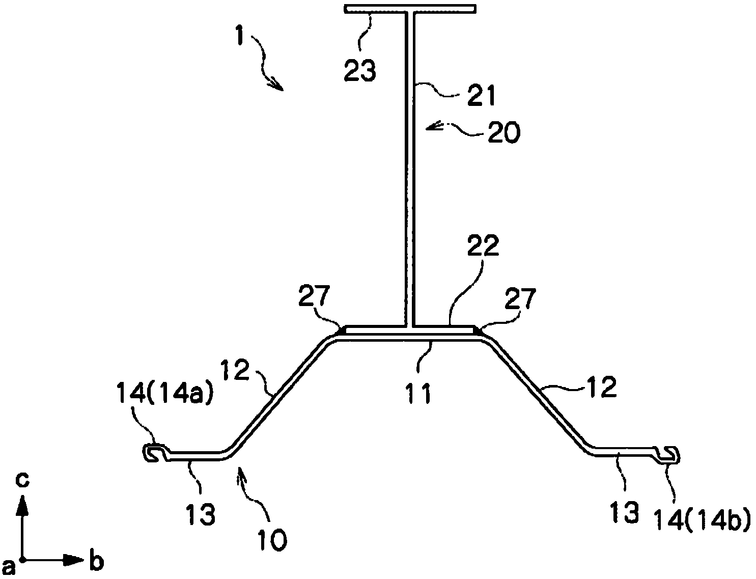
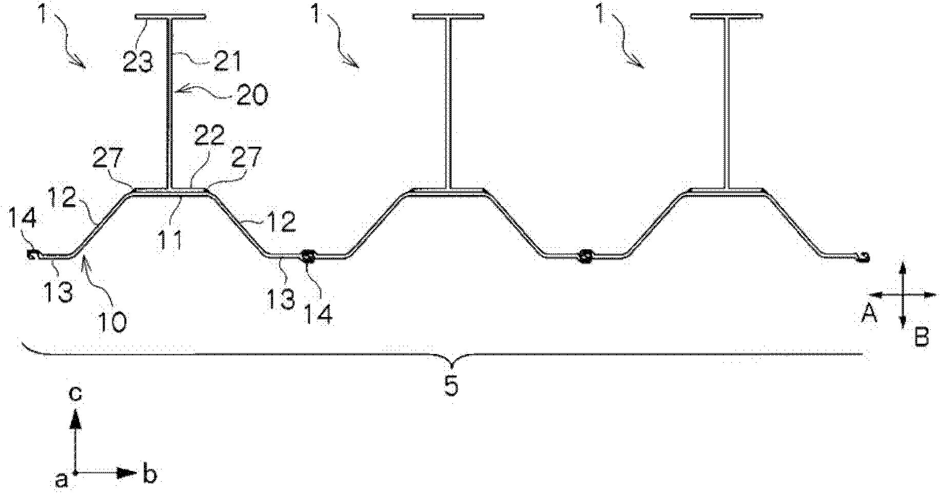
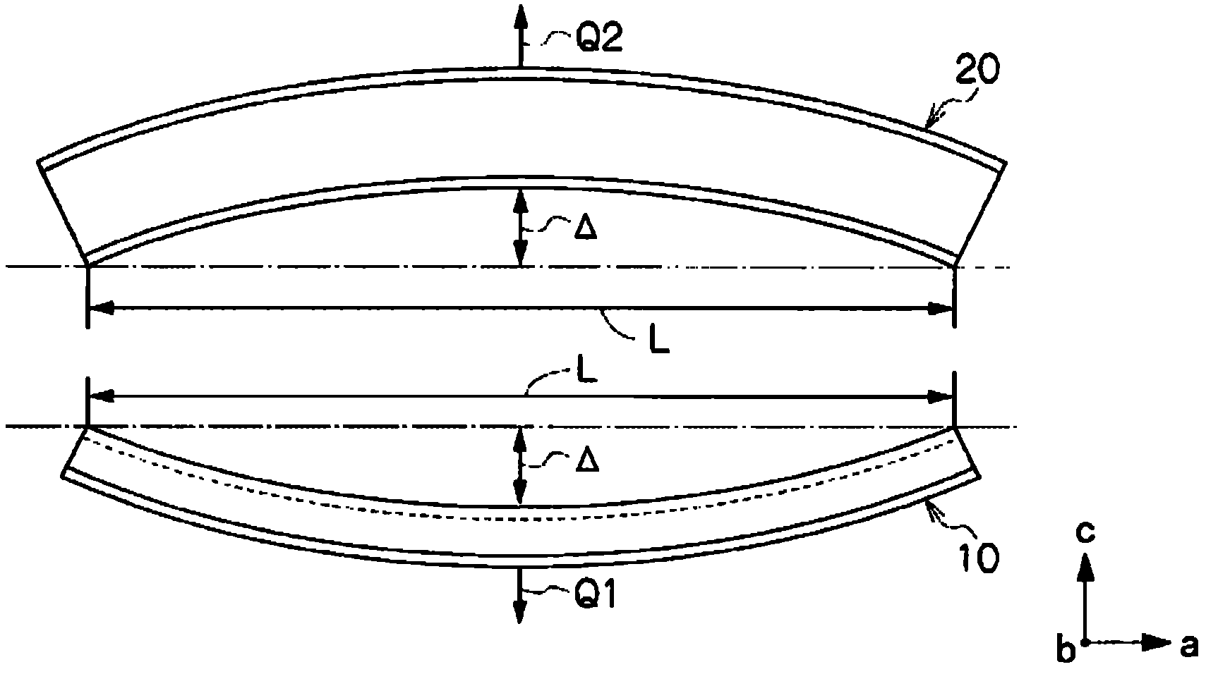
[0143] Hereinafter, the effects of the present invention will be further described through examples. In an Example, the steel materials 1 for underground diaphragm walls were assembled by applying this invention from the steel sheet pile 10 which has the dimension, bending deformation rate, and warpage deformation rate shown in following Table 1. As the steel sheet pile 10, the effective width is 900 mm, the height is 230 mm, and the cross-sectional area per sheet is 110 cm. 2 , The secondary moment of section of each piece is 9430cm 3 The hat-shaped steel of type 10H uses a structure with a height of 700 to 900 mm as the H-shaped steel 20 , and a structure having the same length in the longitudinal direction as the steel sheet pile 10 and the H-shaped steel 20 is used. The H-shaped steel 20 uses the structure which has the bending deformation rate of the same grade as the steel sheet pile 10, and the curvature deformation rate in the direction opposite to the bending of the ...


PUM

PropertyMeasurementUnit
heightaaaaaaaaaa

Abstract

A method of manufacturing a steel material for an underground continuous wall is provided with: a facing step for causing a web section of a steel sheet pile and a flange section of H-shaped steel to face each other; a first fixing step for fixing the steel sheet pile and the H-shaped steel together at a first fixing position; a bend correcting step for correcting both a bend of the steel sheet pile in the width direction thereof and a bend of the H-shaped steel in the width direction thereof by deforming the steel sheet pile and the H-shaped steel; a second fixing step for fixing the steel sheet pile and the H-shaped steel together at a second fixing position separated away from the first fixing position in the longitudinal direction of the steel sheet pile; and a welding step for welding steel sheet pile and the H-shaped steel together in the longitudinal direction of the steel sheet pile.

Description

technical field [0001] The invention relates to a method for manufacturing steel materials for underground continuous walls used for building underground continuous walls in the field of civil engineering. Water wall etc. to use. [0002] This application is based on and claims priority to Patent No. 2009-030310 filed in Japan on February 12, 2009, and the content thereof is incorporated herein. Background technique [0003] In the field of civil engineering and construction, steel sheet piles are generally used as steel materials for underground continuous walls when constructing underground continuous walls used as retaining walls to prevent soil and sand from collapsing, or retaining walls to support filled or cut soil. In recent years, in order to improve the cross-sectional performance of steel materials used as underground diaphragm walls, proposals such as Figure 13 The steel materials 101 for underground continuous walls which fixed the H-shaped steel 120 to the st...

Claims


Application Information

Patent Timeline
Patent Type & Authority Patents(China)
IPC IPC(8): E02D5/04B23K9/00B23K31/00E02B3/10
CPCE02D5/04
Inventor 寺崎滋树豊岛怪原田典佳永津亮祐
Owner NIPPON STEEL CORP
Why Eureka
Try Eureka