led bulbs for space lighting

一种LED光源、LED芯片的技术,应用在照明装置的零部件、照明装置、照明装置的冷却/加热装置等方向

Inactive Publication Date: 2011-12-28
CAO GROUP
View PDF13 Cites 14 Cited by
  • Summary
  • Abstract
  • Description
  • Claims
  • Application Information

AI Technical Summary

Problems solved by technology

Since most packaged LED devices do not emit light from all directions, there are challenges when designing replacement bulbs that use packaged LEDs that emit light from all directions

Method used


Image

  • led bulbs for space lighting
  • led bulbs for space lighting
  • led bulbs for space lighting

Examples


Embodiment Construction

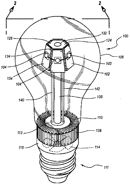
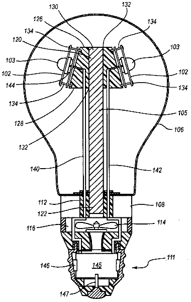
[0011] refer to figure 1 and 2 , shows an embodiment of the invention describing an LED lighting device 100 having a plurality of panels 102 and LEDs 103 mounted to the panels 102, the LEDs 103 being advantageously arranged around a central axis for lighting a space—i.e. , illuminating in a non-unidirectional manner similar to that provided by the use of incandescent light bulbs. Illumination from lighting device 100 is provided by a plurality of LEDs 103 . A glass or plastic bulb (or clear housing) 106 encases the LEDs and various components that are incorporated into the assembled lighting device 100 and are sized so that the bulb 106 looks like a traditional light bulb. If desired, the bulb can be frosted, tinted, or clear, which further lends the appearance of the lighting device 100 to a traditional bulb.

[0012] In one embodiment, the panel 102 is mounted to a faceted bracket 124 . The heat pipe 105 generally extends along the aforementioned central axis and include...


PUM


Abstract

The invention discloses a three dimensional LED arrangement and heat management method using a heat transfer or conduction pipe to enable rapid heat transfer from a three dimensional cluster of LEDs to a heatsink with or without active cooling, the light emitted from the three dimensional cluster not being obstructed by a heat sink arrangement such that the light beam profile generated by the light appears similar to that generated by traditional incandescent bulbs.

Description

technical field [0001] The present invention relates to the field of LED lighting, and more particularly, to concentrated LED lighting fixtures that rapidly transfer heat to a separate heat sink, with or without active cooling, to dissipate heat away from the concentrated LED light source. Background technique [0002] Light emitting diodes (LEDs) are considered an effective light source to replace incandescent lamps, compact fluorescent lamps (CFLs) and other more traditional light sources in order to conserve electrical energy. LEDs use much less energy than incandescent bulbs require to produce comparable amounts of illumination. Depending on the design of the lighting bulb, energy savings range from 40% to 80%. In addition, LEDs do not contain environmentally harmful elements such as mercury commonly used in CFLs. There is a need for lighting bulbs employing LEDs as light sources to replace traditional incandescent bulbs, CFLs, and other traditional light sources to pr...

Claims


Application Information

Patent Timeline
Patent Type & Authority Applications(China)
IPC IPC(8): F21V21/00
CPCF21Y2103/022F21V29/027F21K9/135F21V3/00F21K9/00F21Y2101/02F21V29/006F21Y2111/007F21V29/2231F21V29/02F21V29/677F21V29/773F21K9/232F21Y2115/10F21Y2103/33F21Y2107/40F21V29/67F21V29/51
Inventor 登森·西尔赵辉·林
Owner CAO GROUP
Why Eureka
Try Eureka