Manufacturing method and manufacturing device of electrode plate for paste-type lead storage battery

A technology for lead-acid batteries and manufacturing methods, which is applied in the direction of lead-acid battery electrodes, electrode manufacturing, lead-acid batteries, etc. It can solve problems such as skeleton deformation, exposure of skeletons in collectors, and hindrance to the filling of paste-like active materials. Liquid, easy-to-cover effect

Active Publication Date: 2011-12-28
HITACHI CHEM CO LTD
View PDF5 Cites 2 Cited by
  • Summary
  • Abstract
  • Description
  • Claims
  • Application Information

AI Technical Summary

Problems solved by technology

However, it is not necessarily possible to reliably fill the paste-like active material on the lower surface side of the electrode plate (the side opposite to the surface filled with the paste-like active material).
In addition, in the technique of Patent Document 2, since the current collector is supported by a hard net, there is a case where the skeleton in the current collector is deformed.
In addition, since the hard net is not necessarily arranged at the position supporting the skeleton in the current collector, the hard net may hinder the filling performance of the pasted active material on the lower surface side of the electrode plate.
In addition, there is a problem that the inner skeleton of the current collector is exposed after removing the hard mesh at the part where the hard mesh supports the inner skeleton of the current collector.

Method used


Image

  • Manufacturing method and manufacturing device of electrode plate for paste-type lead storage battery
  • Manufacturing method and manufacturing device of electrode plate for paste-type lead storage battery
  • Manufacturing method and manufacturing device of electrode plate for paste-type lead storage battery

Examples


Embodiment 1

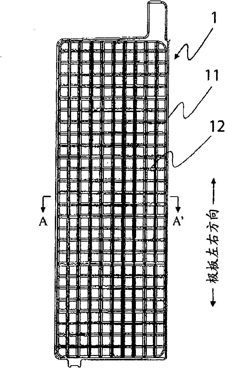
[0061] 1.6% by mass of tin and 0.08% by mass of calcium were added to lead so that the entire molten mixture was a lead alloy of 100% by mass, and a current collector for a positive electrode plate was fabricated by gravity casting. The current collector 1 as image 3 , Figure 4 As shown, a thick inner skeleton 12-1 and a thin inner skeleton 12-2 are arranged inside the frame skeleton 11. The external dimensions of the frame skeleton 11 are 385mm×140mm, the thickness is 5.8mm, and the width is 4.4mm. The cross-sectional shape of the thick inner frame 12-1 is a hexagon whose thickness is larger than the width, with a thickness of 5.4 mm and a width of 4.3 mm. In addition, the cross-sectional shape of the fine inner frame 12-2 is also hexagonal in which the thickness is larger than the width, and the thickness is 3.6 mm and the width is 2.8 mm. Such as Figure 4 As shown, the end faces on the filling surface side in the thickness direction of the thick inner frame 12-1 and ...


PUM

PropertyMeasurementUnit
Thicknessaaaaaaaaaa
Thicknessaaaaaaaaaa

Abstract

The present invention discloses a manufacturing method of a paste type lead acid battery plate and a manufacturing device of the same. The paste type lead acid battery plate is manufactured in which a pasty active material is preferably filled on a lower surface side of a polar plate, and a lattice-formed inner framework of a power collector is prevented from being exposed. In the power collectorwhich passes below a filling machine provided with a hopper in which the pasty active material is stored, the pasty active material is filled, to obtain a polar plate, and the surface of the polar plate is pressed while the filled pasty active material is soft with the polar plate conveyed. At this time, a first pressing process for heavily pressing a first region on a polar plate surface disposed on one side in the width direction of the polar plate, which is perpendicular to the conveying direction of the polar plate and the thickness direction of the polar plate, a second pressing process for heavily pressing a second region of the polar plate surface disposed on the other side of the width direction of the polar plate, and a third pressing process for pressing the polar plate in the overall width direction are carried out at least once, and the third pressing process is carried out at the end of the pressing processes.

Description

technical field [0001] This invention relates to the manufacturing method of the pole plate for paste-type lead acid batteries, and the manufacturing apparatus used for the manufacture. Background technique [0002] Electrode plates for paste-type lead storage batteries have conventionally been produced as follows. [0003] First, lead powder is used as the main component, and an active material material mixed with other required components is mixed with dilute sulfuric acid or water to prepare a paste-like active material. Then, the adjusted paste-like active material is filled on the grid-shaped lead alloy current collector to prepare a filled electrode plate. The electrode plate surface of the filled electrode plate was pressed to obtain an electrode plate in which the filling property of the paste-like active material was improved. After pressing, the filled plates are dried. The current collector has a relatively thick frame frame and a relatively thin inner frame in...

Claims


Application Information

Patent Timeline
IPC IPC(8): H01M4/20
CPCH01M4/20Y02E60/126H01M4/73H01M4/0435Y10T29/49204Y10T29/53204Y10T29/10Y10T29/49112Y10T29/49108Y10T29/49002Y10T29/53135Y02E60/10H01M10/06
Inventor 玉野贵大大野周平金泽俊彦畠中俊和
Owner HITACHI CHEM CO LTD
Why Eureka
Try Eureka