

Magnetic coupler and gap tank for magnetic coupler
A magnetic coupler and gap technology, applied in the direction of permanent magnet clutch/brake, electric brake/clutch, electromechanical device, etc., can solve the problems of uneconomical and expensive manufacturing, and achieve the effect of no eddy current loss
- Summary
- Abstract
- Description
- Claims
- Application Information
AI Technical Summary
Problems solved by technology
Method used
Image

Examples
Embodiment Construction
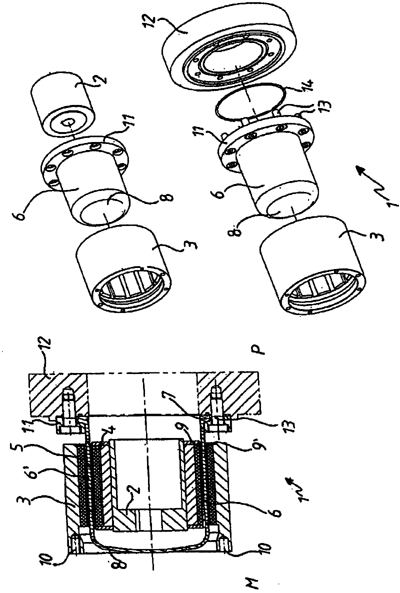
[0028] figure 1 A perspective view showing the structure of the magnetic coupler 1 of the invention on the one hand, and a partially assembled state of the magnetic coupler 1 on the other hand. The magnetic coupler 1 includes the following main components:
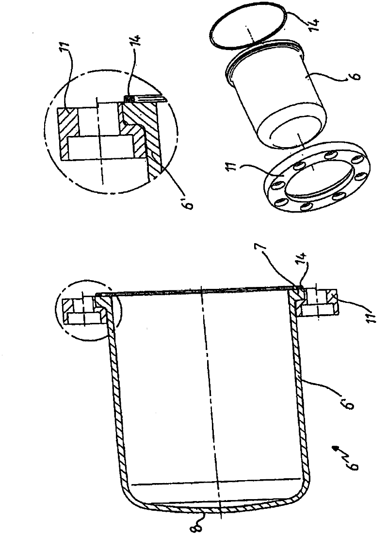
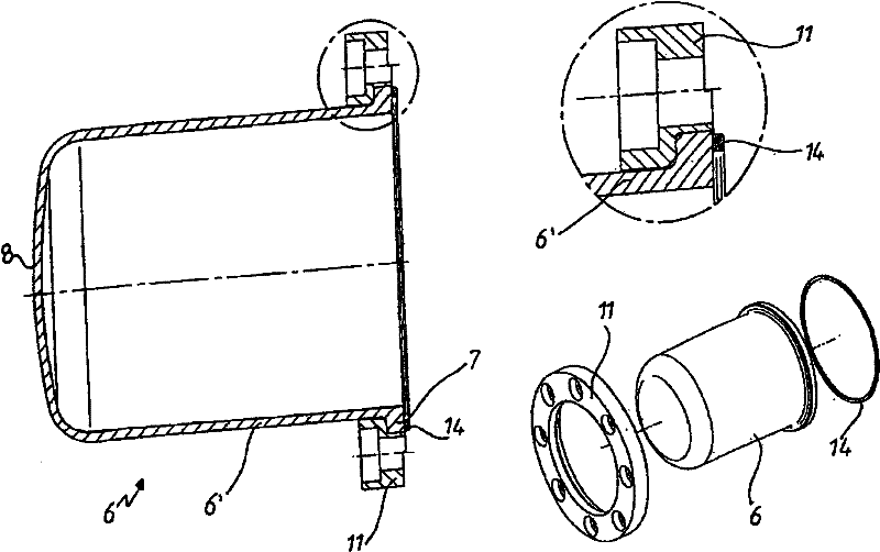
[0029] An inner rotor 2 , an outer rotor 3 , both equipped with corresponding magnets 4 , 5 , and a slotted pot 6 . The slot tank 6 has a flange 7 and a closed bottom 8 . The tubular section 6 ′ extending between the base 8 and the flange 7 is here positioned in the air gap 9 , 9 ′ between the magnets 4 , 5 with a minimum gap (+ / - 0.1 mm). According to the invention, the slot tank 6 is made of borosilicate glass, which is particularly resistant to chemical materials and pressure, temperature fluctuations and has a size of less than 4×10 -6 / K coefficient of thermal expansion. When installed, the motor side M and the pump side P are exposed. On the motor side, threaded holes 10 are introduced in the outer rotor, on whi...
PUM
 Abstract
Description
Claims
Application Information