
Descent control device

The technology of a descending device and a casing is applied in the field of safety rescue devices, which can solve the problems of heavy weight, inconvenient to carry and use, and not compact, and achieve the effects of good stability and reliability, convenient installation and use, and simple structure.

Inactive Publication Date: 2012-01-04
天津吉港黑马自行车有限公司
View PDF2 Cites 5 Cited by
  • Summary
  • Abstract
  • Description
  • Claims
  • Application Information

AI Technical Summary

Problems solved by technology

However, most of the descending devices in the prior art are complex in structure, not compact, large in size, heavy in weight, and inconvenient to carry and use

Method used


Image

  • Descent control device
  • Descent control device

Examples


Embodiment Construction

[0010] In order to enable those skilled in the art to better understand the technical solutions of the present invention, the present invention will be further described in detail below in conjunction with the accompanying drawings and embodiments.

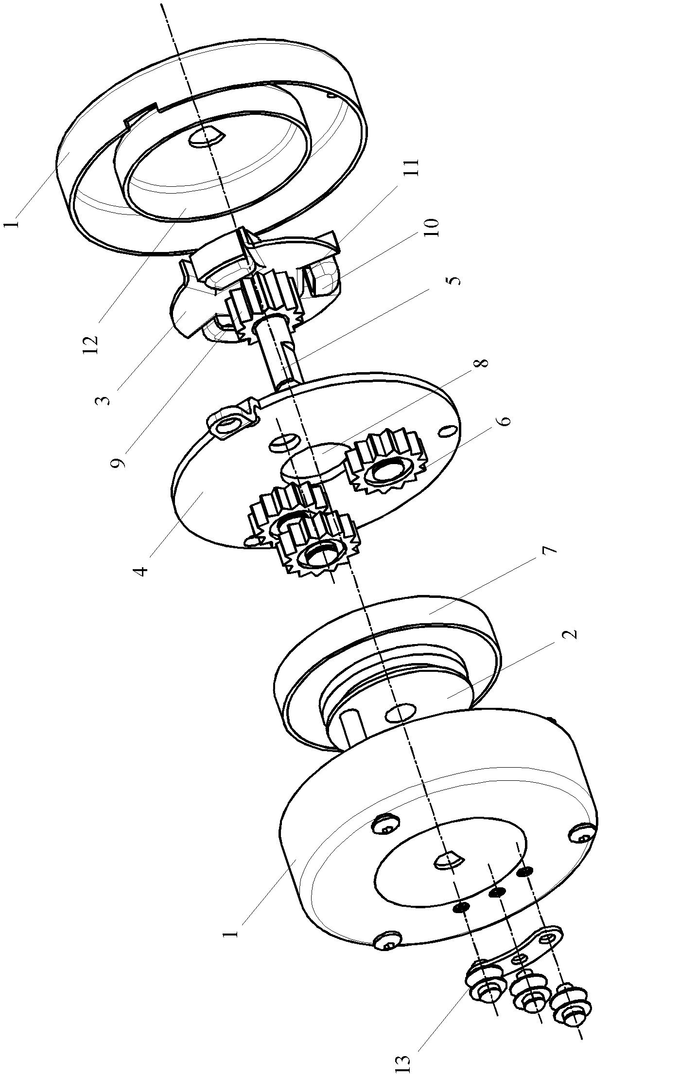
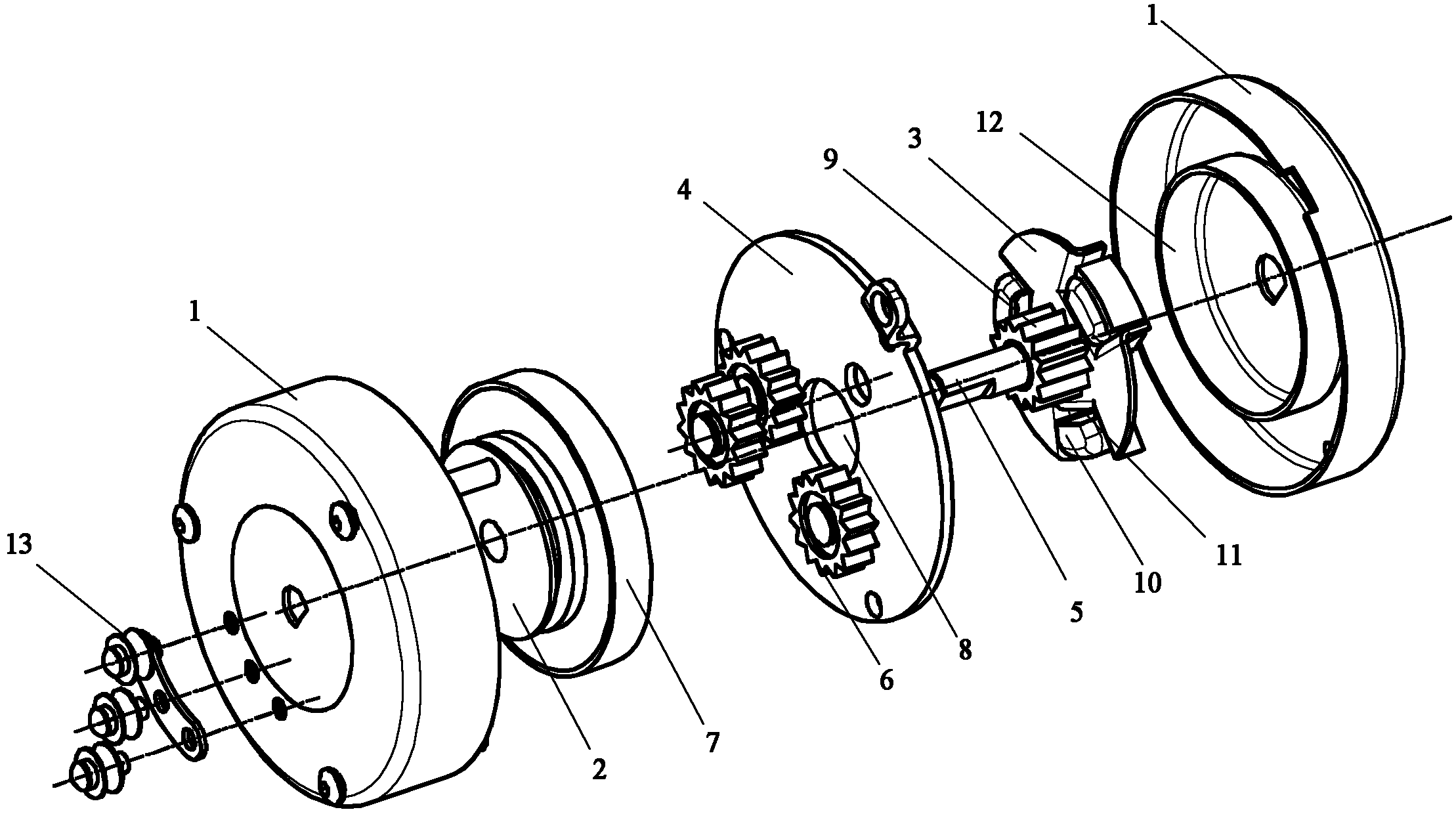
[0011] Such as figure 1 As shown, the slow descender of the present invention includes a casing 1, a rope wheel 2, a brake wheel disc 3 and a main body bottom plate 4, wherein the rope wheel 2 and the brake wheel disc 3 are installed inside the shell 1 through a shaft 5, and the main body bottom plate 4 is located at Between the rope wheel 2 and the brake disc 3.

[0012] Three planetary gears 6 are installed on the side of the main body bottom plate 4 close to the sheave 2, and the internal gear 7 is fixed on the side of the sheave 2 close to the main body bottom plate 4, and the planetary gears 6 and the internal gear 7 are meshed.

[0013] A through hole 8 is opened in the center of the main body bottom plate 4, and three plan...


PUM


Abstract

The invention discloses a descent control device with simple structure and higher reliability. The descent control device comprises a shell, a rope sheave and a braking rotary table, wherein the rope sheave and the braking rotary table are installed inside the shell through a shaft; the shaft is fixed inside the shell; the braking rotary table is provided with a friction block; the friction block is installed in a sliding chute of the braking rotary table; a friction wall is located inside the shell and corresponds to the friction block; a main body bottom plate with a through hole at the center is fixed inside the shell and located between the rope sheave and the braking rotary table; one or a plurality of satellite gears are installed on one side, which is close to the rope sheave, of the main body bottom plate; the satellite gears are meshed with an inner gear; the inner gear is fixed with the rope sheave; and an outer gear is fixed on the axial line of one side, which is close to the main body bottom plate, of the braking rotary table, passes through the through hole at the center of the main body bottom plate and is meshed with the satellite gears. The descent control device disclosed by the invention has the advantages of simple and compact structure and good stability and reliability, and is convenient to install and use.

Description

technical field [0001] The invention relates to a safety rescue device, in particular to a descending device used for high-rise escape. Background technique [0002] The descending device is composed of hooks or rings, slings, ropes and speed control, etc. It is a safety rescue device that allows people to descend slowly along the ropes. It can be installed on building windows, balconies or flat roofs of buildings with special installation equipment, and can also be installed on elevating fire trucks to rescue victims in high-rise buildings on fire. The slow descending device is suitable for high-rise escape. When working, the slow descending rope drives the planetary gear reduction mechanism in the main engine to run and friction with the friction block in the friction hub to ensure the safety of the user and slowly descend to the ground. However, most of the descending devices in the prior art are complex in structure, not compact, large in volume, heavy in weight, and in...

Claims


Application Information

Patent Timeline
Patent Type & Authority Applications(China)
IPC IPC(8): A62B1/10
Inventor 王荣生
Owner 天津吉港黑马自行车有限公司
Learn More